In a our college, every student chapters organize the first program in which they inform the fresher’s about their student chapter and the activities done by them throughout the year. Similarly the Orientation program of Cutting Edge Visionaries (CEV) was organized on 3rd September 2015.
In this Orientation program, students were given information about the college, life at college, facilities provided by the college, proper methods of utilizing the provided facilities, how can they be productive in the spare time etc. They were provided with various information, from which projects they can do to which TV shows and movies they should watch. All the information was provided to them.
The main aim of the program was to make the students productive, get involved in creative activities whether it may be technical or non technical. The sole idea of CEV is that people learn something new, something different and share that with the people in the future.
All those who were not able to attend, may contact your friends those who attended and take the given handouts.
Google projects tend to have a forward focus. The company pours resources into researching everything. In past the company had come forward with many projects like Google Maps, Google Glasses, Google Goggles, driverless car etc. which have changed the life and made it easy.
Similarly some of the new upcoming popular projects that Google is putting resources into development are:
Project ARA
Project SOLI
Project JACQUARD
PROJECT ARA:
The smartphone is one of the most empowering and intimate objects in our lives. Yet most of us have little to say in how the device is made, what it does, and how it looks. And 5 billion of us don’t have one. What if you could make a thoughtful choice about exactly what your phone does, and use it as a creative canvas to tell your own story?
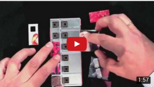
With this idea, Google came forward with the Project ARA. Project ARA is the codename of an initiative that aims to develop an open hardware platform for creating highly modular smartphones. The platform will include a structural frame or endoskeleton that holds the smartphone modules of the owner’s choice such as a display, camera, speaker, processor or an extra battery.
The project was originally headed by the Advanced Technologies and Projects team within Motorola Mobility while it was a subsidiary of Google and was working in collaboratively with Phonebloks. Although Google had sold the Motorola to Lenovo, it retained the project team.
ARA smartphones are built using modules inserted into endoskeleton frames which will be the only component in the ARA smartphones made by Google. The modules that are attached to the frame by electro-permanent magnets can provide common features such as camera, speakers, display, etc. as well as some specialized features like medical devices, printers, projectors, night vision sensors or game controller buttons.
Google wants Project ARA to lower the entry barrier for phone hardware manufacturers so there could be “hundreds of thousands of developers” instead of the current handful of big manufacturers. This would be similar to how the Google Play Store is structured. Lowering the barrier for entry allows many more people to develop modules. Anyone would be able to build a module without requiring a license or pay a fee.
PROJECT SOLI:
One of the big problems with the wearable devices right now is inputs–there’s no simple way to control these devices. Also at a time when most gesture–sensing technology is unreliable and clunky, Project SOLI, one of Google latest cutting–edge experiments from its ATAP group, provides an enticing example of the type of powerful motion controller that could actually change how we interact with everything from smart watches and tablets to appliances and other everyday objects.
Unlike gesture control tech that came before, Google unveiled an interactive sensor that uses radar to translate subtle hand movements into gesture controls for electronic devices. The sensor is able to track sub-millimeter motions at the speedy rate of 10,000 frames per second and with exceptional accuracy. Not only that, but it fits onto a fingertip sized chip and can be used in everyday devices.
Using radar is a fundamentally different approach to gesture tracking because unlike camera-based system which uses a lens, the radar used in Project SOLI will travel through certain materials, making it possible to place chip inside devices and out of sight.
The basic working principle of the system is that it beams out a continuous signal that gets reflected by arm so it measures the difference between the emitted and received signal. It’s a very complex wave signal and from that the system provides signal processing and machine learns the technique to detect the gestures.
The gestures chosen by the team while tests were selected for their similarity to standard action we perform every day. For example, rubbing thumb and finger could be used for volume control,swiping across the side of a closed index finger with the thumb could be used for scroll across a flat plane, while tapping a figure and thumb together would press a button.
Google’s ATAP department is already testing hardware applications for the technology and we can hope to use this technology in near future.
PROJECT JACQUARD:-
Till now we have heard a lot about the wearable gadgets and might have even used them but how would it be to make the wearable’s that we can actually wear. Yes! Those days are not far. Google’s new Advanced Technology and Project group is trying its hand at manufacturing high-tech fabrics and wearable electronics that you can actually wear with Project JACQUARD and for this it has signed a partnership with Levi Strauss & Co.
Project JACQUARD makes it possible to weave touch and gesture interactively into any textile using standard, industrial looms. Everyday objects such as clothes and furniture can be transformed into interactive surfaces.
Jacquard yarn structures combine thin, metallic alloys with natural and synthetic yarn like cotton, polyester, or silk, making the yarn strong enough to be woven at any industrial loom.
Using conductive yarns, touch and gesture- sensitive areas can be woven at precise locations, anywhere on the fabric. Alternatively, sensor grids can be woven throughout the textile, creating large interactive surface.
The complementary components are engineered to be as discreet as possible. Google developed innovative technique to attach the conductive yarns to the connectors and tiny circuits of size not larger than a button. These miniaturized electronics capture touch interactions, and various gestures can be inferred using machine-learning algorithms.
These captured touch and gesture data can be wirelessly transmitted to the mobile phones or other devices to control wide range of functions, connecting users to online services, apps, or phone features.
Jacquard components are cost-efficient to produce, and the yarns and fabrics can be manufactured with standard equipment used in mills around world.
Connected clothes offer new possibilities for interacting with services, devices, and environments. These interactions can be reconfigured at any time. Further Jacquard is a blank canvas for the fashion industry. Designers can use it as they would and add new layers of functionality to the designs, without learning about electronics.
Though Google is not the first one to create conductive threads, startups like OmSignal and Sensoria are currently selling shirts and running socks that contains such threads and use their electronics innards to track various metrics associated with physical activity. But Google is trying to combine the radar based Project SOLI with this Project JACQUARD which might be a revolutionary concept.
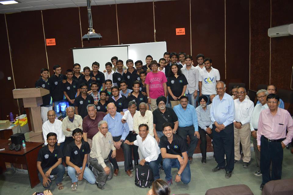
The alumni of 1965-70, amongst the earliest batches of SVREC had a joyous reunion, remembering their youthful days of college, how they went ahead in life and made their efforts worth its weight in gold! Of the glorious gathering of around 25 alumni , we the current generation of SVNITians had the honour of knowing, hearing and connecting to them through a CEV Talk entitled “Interactive Session by SVNIT Alumni of Batch 1970” on 8th February,2015.
cev team with alumni of ’70 batch
The first talk was delivered by Mr. S. Neelakantan (Retd Scientist ‘G’, Group Dir., Helicopter and Fighter Aircraft DRDO) entitled “Helicopters- Concepts and Development” wherein he discussed about the fundamental concepts & history of Indian Helicopter Technologies, development of indigenously built Advanced Light Helicopters- Dhruv, its design, development tests & certification. Prospects of future advanced warfare & tactical helicopters along with their robustness was also shared.
In one of the most interactive sessions, Mr. Sailesh Lakdawala , Energy Consultant , Duke Energy, USA gave insights on power generation, working and reliability of Nuclear Power. He discussed the current scenario of Nuclear Power Generation in USA, India and rest of the world. This interesting talk also discussed about Fukushima Daiichi Reactor failure, Chernobyl Disaster, Thorium Reactors, Breeder vessels, Small Modular Reactors, Pressurised Water Reactor & Boiling Water Reactors.
In yet another captivating talk, Mr. Harsh Thakkar , Senior Consultant, National Grid USA emphasised the importance of System Protection and also gave us the optimism of honing entrepreneurship skills by giving an example of Green Light Planet , a Forbes 30 under 30 (2012) start-up founded by his son Mr. Anish Thakkar. In end we had an overview of current Elevator Technology by Mr. Satish Mandirwala, Eskay Elevators.
It was heart rendering to interact with alumni who had such diverse backgrounds such as US Navy Weapon Systems, Indian Army, Super Alloy Project, Mining Industry etc.
We thank all the alumni for sharing valuable lessons and ethics important for all to succeed in life. We also extend gratitude to Dr. PD Porey, Director, SVNIT, Mr. Utpal Mistry President & Mr. Kamal Parekh Hon. Secretary of SVNIT Alumni Association for extending their help in making this event a grand success. We also thank all CEVians for working hard to put together a successful informative session and the wide spectrum of audience that came to listen the golden words of wisdom of their alumni.
Everything you need to know about Android, Motorola, Google, Tizen and the future!
Samsung launches Tizen phone in CES 2015 (Though at first sight it’s look like Android phone).
Is this the simple news for you? But it’s not.
Why Samsung needs to unveil a whole new OS based smart phone? Did sell of Samsung Android phone decreases? In market scenario in 2011-12, Samsung is doing good in smart phone market across the world. And keep increasing their turnover. This whole idea of new OS came after the Deal. The Deal between Google Inc. and Motorola Mobility. The Deal worth $12 billion. The Deal which was an investment to dive head first into the smart phone market in US for Google Inc.
After this deal of $12 billion between Google Inc. and Motorola Mobility, Google became smart phone manufacturer as well. And Samsung was afraid that Google might overtake the market and they will be in difficulty. From then Samsung started working on the project called ‘Tizen’ and launches its first beta version on 5th January, 2012 just after few months of acquisition of Motorola Mobility( on August 15th,2011).
“We welcome today’s news, which demonstrates Google’s deep commitment to defending Android, its partners, and the ecosystem.”
– J. K. Shin. President, Samsung, Mobile Communication Division on August 15, 2011 when Google announced an agreement to acquire Motorola Mobility.
We’re just two weeks into 2015, but Samsung’s already made more progress with its in-house Tizen OS. There’s finally a real Tizen smart phone (Open-source but not “The Android”), and the Korean company promises that the rest of the year will bring “a flood of devices” running its operating system. ( Though at this time Tizen Application store is having very few number of apps). Company has claimed that the Tizen-powered smart watches, cameras, TVs, and the new Z1 smart phone that we’ve seen so far are “just the tip of the iceberg”. Tizen will be a crucial part of Samsung’s future IoT(Internet of Things) strategy, helping to connect and smarten up devices and appliances around our homes and beyond. Samsung says it “requires less processing power and memory, thereby ensuring faster device speeds while consuming less energy.” Tizen is being compared with Google’s Android platform. Android is expanding beyond its smart phone origins with tailored versions like Android Wear and Android TV serving the emerging connectivity needs of specific device categories.
Main aim of Samsung for this step might be to diversify away from its dependency on TechGiant Google. And to cut down the monopoly of Google over smart phone OS. The Korean company is keen to make sure that they achieve this, at least in part, through the use of its own software. To encourage developers to jump on board and help build an ecosystem around its anticipated Tizen deluge, Samsung points out that it sold 665 million devices last year, which “could convert into a lot of Tizen.”
Tizen is still far from being able to challenge Android on phones (and it’s doubtful that it’ll ever get there), but the way it’s being positioned and promoted by Samsung in other areas, puts it in direct confrontation with Google’s expansionary plans. No matter how compromiser Samsung’s tone may be, today’s announcement of an expanding Tizen OS is a clear signal of its intent to challenge and compete with Google for the next wave of connected devices.
In short cold war has begun between Google Inc. and Samsung Electronics Pvt. Ltd. It is actually good for customers.
Hmm before I talk about this let me ask you a question. Who has watched the movie “back to the future”? If the answer is yes then good but if it is no then I would recommend you to watch it. Apart from a good story, what the movieportraysis a lot of cool gadgets and the mosteye catchingone is the coolHoverboard.
Well for those of you who don’t know what aHoverboardis, imagine it as a normal skateboard but with no wheels and lifted (or I would say hovering) a few inches above the ground. Long story short it is just like a flying skateboard, sounds cool right!!!
So coming back to the point why I am talking about aHoverboardis because it has actually become a reality. Yes I said it right we have invented aHoverboard, well not we but people working at the companyHENDOhave. No, it’s not a hoax but they have actual proof that theHoverboardworks and to prove it they literally gave it to the legend Tony Hawk to have a ride! A small demonstration can be seen in the pic below.
Hoverboard
So how does it actually work? Well the company says that it usesfourhover-engines utilising ‘Magnetic Field Architecture’, to break it down it uses an opposing magnetic field from the surface below. Well in simple terms what the engines do is that they have some permanent or electro-magnets in them with changing magnetic fields . Due to this changing magnetic field eddy currents are produced in the conducting surface below which tends to generate its own magnetism. According to Lenz’s law the field so produced is in opposition to its cause and hencedue torepulsion the board is able to hover. An illustration is given below.
Lenz’s law
Obviously the technology behind it is very advance with the use ‘Dynamic magnetic suspension’ and ‘halbach array’ etc. Both of these technologies are currently in use in Magnetic levitation trains.
Well one major drawback in these boards is that they require metallic sheets as surface below to actually produce this effect but the company says that they are working on some more compounds. Plus the board comes at a price of a whopping 10,000$ but they do provide a ‘white box’ developer kit at a price of 300$ so that you can get an idea of how the board works and apply it anywhere. The company is open to any new developments suggested by anyone on how to improve their technology…..now that’s cool!!!
Well to sum it all up I can say that the day is not far behind when we could actually use a Hoverboard (literally flying) to move from one place to another .
In this quickly growing world of technology, people have become so addicted to smartphones, tablets, iPods and this entire virtual online world that they sometimes don’t even realize that they exist in a real world. Since these device don’t work on food and water there comes this huge issue of giving power to these devices and thus comes the term charging of the batteries present in these devices and as soon as the word charging comes our head becomes full of tangled wires. So to deal with this, now scientists have developed a new technology for wireless transmission of power. It basically works on a concept called RESONANT INDUCTIVE COUPLING. This concept is very easy to understand so please don’t be scared and astonished by hearing such a complicated term. Actually to understand this concept you only need your 12th std physics. So there are basically three words ‘resonant’, ‘inductive’ & ‘coupling’. Let us revise the meanings of these words in context of physics.
Firstly resonance, in simple words resonance happens when the amplitude of a wave (in this case an electrical signal) maximizes at a certain frequency. In our case this is important as we want to ensure maximum electrical power transfer.
Now electromagnetic induction, in our case we are talking about mutual inductance which in short is just induction of voltage or an emf in a coil when a variable current carrying coil is kept in its vicinity.(of course lesser the distance higher the induction)
Last but not the least coupling is just used as both the coils are electrically coupled (not physically).
So now if you take all these three things together in your mind as one joint concept then I believe your previous review of the term being complicated will change a bit.
Hence by this I guess you can easily understand how power can be transmitted wirelessly and so nowadays whatever wireless chargers you see simply just consist of two coils one is the transmitter and the other one is the receiver. High frequency (resonant frequency) signals are first generated before the transmitter and then after the receiver receives the signal, the signal is rectified to whatever DC output is required for the device.(high frequencies are used so as to decrease the losses through the air i.e to decrease the leakage flux)
There are a lot of advantages as we can see there is no need to deal with the long and tangled wires, and we don’t even have to stay very close to our power sockets.
One more big benefit is that we can simultaneously charge one or more devices with just one setup as you can see in the figure beside-
But on the downside there is also a fact that we have to make a great sacrifice on efficiency as we increase the distance between the two coils the leakage flux through the air increases which in turn decreases the power transferred. Another problem is the range of the distance at which the two coils are kept because after some distance there will be no power transmission but for that a solution that is being proposed is that we create a network of all the transmitter coils at suitable distances so that the receiver can receive power suitably from all the coils.
Also there are alternate options available other than resonant inductive coupling like Conductive Connections, Radio Transmissions and Wi-Fi.
As you people are wondering how even scientists have named this phenomenon in such an interesting way. In this project I’m going to tell you what a Joule Thief Circuit is how easily it can be made and also a bit of how it works. Coming back to the name ‘Joule Thief’ actually signifies that we are going to steal something and that is power. This power is said to be stolen as we are going to extract it from dead pencil cell (AA) batteries. Actually it isn’t theft because these batteries that we feel have gone dead are never completely exhausted, there’s always some residual power left inside them after our usage and this is power is sufficient to run a Joule Thief Circuit.
Now regarding the construction of this circuit, it is very easy to make and can be made with a few basic components. The main components are transistor (2N4401, BC337, 2N3904), LED, Toroid Bead (ferrite core), Thin wire (it should be insulated as found in a motor) and of course dead 1.5V AA type pencil cell that you use daily. Amongst these components the one that is truly tough to find is a toroid bead. You can get it in an electrical equipment store or else you can find it in an old CFL. But take care while removing it from the CFL because you will have to open the entire CFL and you might break the glass. So after opening the CFL there will be a PCB on which you may find your toroid bead. Also another option is that you can take it out from an old motherboard of a PC. It is actually a hollow cylindrical bead made up of magnetic material (test it with a magnet), so that it can act as a core for the inductor that we are going to make for this circuit. The circuit connections are given below:
The process of making this mainly consists of soldering all the parts according to the circuit diagram given and winding the toroid bead with the thin insulated wire.
For the detailed information regarding how to make it you can go to this link:
So if you have made it then you’ll be able to see how nicely a dead battery can make the LED glow so bright. But our journey doesn’t end here since we have to know what wonders are actually taking place inside this small piece of circuitry. Just for finding things out, I had actually taken an LED that turns ON at a minimum voltage of 3V. This means that no matter even if I try to directly connect the LED to a brand new 1.5V pencil cell, then also the LED won’t glow (and believe me I did try connecting the LED to a new cell and it didn’t glow even a bit). Only if you would connect two new 1.5V cells in series, the LED will glow. You might be thinking that there would be some kind of voltage amplification involved over here. Well after you’ve made it, take a DMM (digital multimeter) and check the output voltage across the LED. You will be shocked as I was to find out that the DMM shows you a voltage of just 1.5V or even less than that. Now you check the input voltage across the battery and you will find that it is more or less same as compared to the output voltage. Then how is the LED glowing? Initially I had tried glowing the LED by connecting it directly to the new 1.5V cell, at that time it didn’t glow; but if I connect the LED to this circuit it glows brightly having the same output voltage (1.5V). After getting these results I started reading about this on the internet and also consulting various people as to why this was happening. Then I came to know that actually the transistor is the reason for all this. The inductor made with the toroid gives an instantaneous voltage boost to the transistor and the transistor here is acting as a switching device.
So what happens is that the DMM is misleading us to false conclusions. The DMM always shows the average voltage across the output terminals. Thus, in reality there would be some voltage amplification (which is enough for the turning the LED and in our case greater than 3V) and then the output waveform would also have a particular duty cycle for which it gives a higher voltage. For finding out the exact values of the amplified voltage and for what percentage of the duty cycle we are getting the high voltage you need to check it on a DSO (digital storage oscilloscope). Here is an image of a sample output waveform that you might get in a DSO for this circuit.
As you can see the frequency of the switching by the transistor is very high (38.46 kHz). Hence, due to persistence in human vision we cannot make out, but in reality whenever the spike in the voltage occurs (the transistor turns ON) the LED glows for a very small amount of time and then it turns off for the remaining 60 to 70 % of the cycle. Since this happens at a very fast rate our eyes can’t judge it and we think that the LED is glowing for the whole time. The brightness will be decided by the amount of current that flows through the transistor and thus transistors like 2N4401 or BC337 are preferred as they can provide more current.
Hence, we have made a device which actually runs from very small power taken from dead batteries and don’t worry that since it is a dead battery, the LED will be ON for a long time. I have tested it and it keeps on glowing for a few hours. So what I actually made out of this concept is an emergency torch. Just that instead of one LED I connected a few more LEDs in parallel and made a bunch of it in a packed case and there it is I had a wonderful torch which ran on dead batteries. So remember not to throw out these dead batteries, they can come handy during emergencies.
This project illustrates a very new and a unique method for controlling a multi-purpose robot. This method can actually be used in the control of high functionality drones.
In very simple words if I have to explain this I will say that this method allowed me to control my bot which has a Wi-Fi connection available in its area and on the other hand I am sitting in some corner of the world with my laptop. I can view the surroundings as well as the movements of my robot and also control them from my laptop.
So now following are the essential pre-requisites that you may require for doing this project:
Good knowledge of microcontrollers
Web-development, basics of making a website and also JavaScript.
Through this project I have actually demonstrated an example of the concept of ‘Internet of Things’ (IoT).
Here I have used a device called the SPARK core which is nothing but a combination of a 32-bit MCU (STM32F4) and Wi-Fi module (CC3000) which is interfaced with a basic function robot and an IP-Camera installed on it. Apart from this we had made a website on which we can see the live video feed of the IP-camera installed on the bot and it was through the same website that we sent our instructions to it.
So what the user needs to do is just send his instructions through the website and then through the internet, then the SPARK core (which is already connected to the Wi-Fi) would receive these commands and perform its functions accordingly.
At the same time, the IP-camera which is also connected to the Wi-Fi along with the spark core gives back the live video feed to the website. This IP camera had two servo motors inside it such that it could move about its own axis (360deg) and also 180deg from the surface level. Also it had night vision enabled which increases the bot’s usability.
The heart of this project is the SPARK core on which if you need more detailed information you can find it on https://www.spark.io/ . Now apart from all the technical superiorities that this device has, the main innovative thing about SPARK is the spark cloud which is allotted to every core and is unique for each of them. This spark cloud is nothing but a virtual space or in other words it acts as a control room for our spark core. This control room (spark cloud) can be accessed through the internet if the unique spark core ID and its access token (password) of that particular core is known to us. Each spark core coordinates with its own cloud through the Wi-Fi connection. The spark cloud has a unique way of working. We can write and compile the programs that we want to execute on the core through the cloud. All the programs can be burned directly to our spark core from this spark cloud. Now to access and make changes in the programs in our spark cloud there is a prebuilt online API (application programming interface) developed by the spark community. So the program can be written online on the API on a PC and then the code is transmitted to the core. (Note: for this the core should also be online and connected to the cloud) This gives a huge benefit compared to other systems where we have to manually burn our code onto the microcontroller. Hence the programs can be edited even if we are far from our robot making our system dynamic in true terms. Regarding the language for our coding the easiest Arduino is compatible for the core. Their predefined libraries have to be used at numerous instances. Like for example if some of the functions are required to be available throughout the API (i.e. not just the core). These functions are declared as “Spark.function”.
Initially when the spark core connects to the Wi-Fi, it should be done manually from a PC using the USB port that is available in the core. But once if the spark core is synchronised with a Wi-Fi network then we need not repeat the process again. Then only the core needs to be powered up and it will automatically connect itself to the cloud and it will start syncing with the instructions that have been given through the spark cloud.
Now coming to the website part, the movements of the bot are controlled by the direction keys of your keyboard. The backhand of the website (JavaScript) was designed in such a fashion that the controlling stays very intuitive and you may feel like you are playing a real life racing game. What happened in the background was as soon as the key is pressed, in the background a special type of http request is fired (for spark cloud). Whenever this kind of http request is fired, some predefined function from the program on the SPARK cloud is called that we had initially written on the API for the further operations. The SPARK cloud in turn commands the core which is online to move the bot in some direction. Hence when such multiple http requests will keep getting fired to the spark cloud (since we are constantly pressing the keys), the cloud will constantly send the corresponding instructions accordingly to the spark core to move the bot in the respective directions.
This system can have a wide range of applications in military applications, surveillance purposes, industries, etc. wherein with some safety modifications we can even send this robot in inhumane conditions.
This project was done by me for a firm “GlowLogic Media Pvt Ltd” in Mumbai and also I had help from two of my colleagues who had handled the web-development part.
Children and artists usually possess a plethora of colours, and yet many a times, fail to find the shade that is “just right” for them. Moreover, the numerous colour pens/pencils that everyone owns, produces limitless plastic wastes/ induces deforestation. The catastrophic consequences of both these issues are right before our eyes. Scribble is a device that proves to be an antidote against all these predicaments…
It is a gadget that allows you to choose from 16 million colours while drawing, so you’ll always find the perfect shade and the entire pallet of an artist is held in just a single pen!
All you have to do is hold Scribble’s scanner up to any colour, like on a wall, magazine, fruit or toy and within a second or two, that colour is ready to use. You can instantly draw using the same shade of the “picked” colour – on paper or on your favorite phone, iPad or Wacom Tablet with the Scribble’s stylus pen. The device can hold 1,00,000 unique colours in its internal memory and can reproduce over 16 million unique colours.
Here comes the interesting part of its working. The scribble pen uses a colour sensor and a microprocessor to detect colours. The sensor is embedded at the end of the pen, opposite to the nib and is called the Scribble’s scanner part.
In the ink version of the pen, ink cartridges are used to mix the required colour ink for drawing. The cartridges are refillable and fit inside the body of the pen. They come in cyan, magenta, yellow, white and black. The stylus version works in a similar fashion but does not need cartridges. It rather stores the picked colour in a digital format and the user can doodle on their smartphone or tablet using a dedicated app.
With a considerable battery life of about 15 hours, the pen can draw up to 30 yards. One can easily scan and sync any colour from the pen to an iOS or Android device. It is Photoshop and Corel compatible and enables programming our own dream colours. Moreover, the waste produced by the Scribble stylus is reduced to practically nothing, making it the greenest colouring device ever created!
Such fascinating features surely make scribble a notable invention.
In the following write-up I’m going to tell you all my experiences while I had made my own line follower and will explain all the problems that I had faced along with some tricks to tackle them.
So basically making a line follower can help you in learning simple as well as advanced micro-controller applications that’s why I would advise all the beginners who want to learn micro-controller, your first project should be making an advanced line follower (advanced in the sense that it should be able it to traverse a track of any complication and its functioning should be very smooth). Now I would suggest that all the new learners should have the PDFs of the following essential books:
The AVR Micro-controller & Embedded System – Mazidi
Atmega32 data sheet (since that is the controller I have used)
(You can get these easily on the internet and also can use the link to my drive where you can find all the things that you’ll require in this project of yours
First of all I would suggest some things from my experience:
Don’t use Arduino development board as a learner because once if you have learned how to use any basic micro-controller you will get to know things at grass root level and then afterwards you may find Arduino a cakewalk.
Also don’t use development board available for the Atmega32 micro-controller. Make your own circuit on a General-purpose Circuit Board (GCB). In this way you will learn how to design a circuit and get practice for soldering.
Make your own chassis as well. You need to learn some very basic fabrication also.
Start using simulation software (like Proteus) along with your coding as this will help a lot in verifying your codes. You can’t afford to always burn the code on your micro-controller for checking its validity. In such a situation if you simulate it on the pc then it will be much time-consuming.
Now, the essential things required for a making line follower are Atmega32 MCU, 12V battery, DC motors, chassis, L293D motor driver, LM7805 voltage regulator (5V), Analogue or Digital IR Sensors, laptop, USB-ASP programmer. The MCU runs on 5V, means it will perform its functions within a range of 0-5V. So you need a 5V voltage regulator circuit which can be easily made using two capacitors (1uF and 10uF) and an IC LM7805. Now since our motors run on 12V, we will require a motor driver which converts these 5V signals to 12V i.e. L293D. The circuit connections for both are shown
For coding you need to use the software Atmel Studio. You can learn how to code by using the AVR- Mazidi book and also with the help of the Atmega32 data sheet. There are various extensive examples given in the book which will help you understand the various peripherals of the Atmega32 MCU like Basic Input/Output, ADC, PWM, Timer/Counters, Interrupts, etc.
For a basic line follower you just need to learn basic Input/output functions. Now the basic working principle of a Digital IR sensor is that it gives it will give high or low output according to the strip colour in front of it (black or white).
Once you figure this out then now let’s take an example where you have just 3 line sensors and the track made up of a white line and a black background on the arena. Now in the sensors are lined in such a fashion that if the bot is facing forward then it must have one sensor on the white line and two just reasonably outside it. Thus the sensor at the centre will give output 1(high) and the other two will give output 0(low) (Note: this is not necessary some sensors give inverted output like on black they give 1 and on white they give zero so you need to check this first). These output readings from the sensor are taken by the MCU as an input for further analysis. Now if any of the outer sensors will come inside the track due to the movement of your robot, then that sensor will also start giving 1 and the centre one that was inside might move out of the line and will start giving zero. In such a situation, your code should indicate that the bot needs to move in the opposite direction to get back on the line. Hence you might have 3 possible cases if the centre one is giving 1 then go straight, if the one on the right is giving you 1 then go right and if the left one is giving you 1 then go left.
Regarding the simulation install and run Proteus and then you can see it is very similar to Multisim, hence make your own circuit with the micro-controller, sensors, voltage regulator circuit, motor driver circuit, motors, etc and test it with your code on your pc and by doing this you will save time as well as the safety of your equipments is ensured.
Thus in this way very simply you can control your bot to follow a simple line. Now if you don’t want to use digital sensors and prefer analogue sensors then you need to implement ADC and if you want your bot to move very smoothly then you also have to implement PWM. They are a lot of other concepts and complicated algorithms that are used in advanced line following and rather these bots then almost act as grid solvers.
For AVR beginners there is an excellent YouTube channel that you can refer which will help you understand these things very easily:


 The MCU runs on 5V, means it will perform its functions within a range of 0-5V. So you need a 5V voltage regulator circuit which can be easily made using two capacitors (1uF and 10uF) and an IC LM7805. Now since our motors run on 12V, we will require a motor driver which converts these 5V signals to 12V i.e. L293D. The circuit connections for both are shown