What would you find?
The Bird’s Eye
Real-world approach for the circuits
Voltage Transformation
Rectification
Smoothening Capacitor
Designing a DC source for LED load
Calculating the Load
What should the value of capacitor?
IC 7805
Designing a DC source for motor
LM317
Trimpot
Conclusion
Note: A better-edited version of this blog is available in original MS Word fromat, link below:
https://drive.google.com/file/d/1zbWqzMz4f0d-WwujdY8IQ0DqDEA9RE9-/view?usp=sharing
The Bird’s Eye
We have seen different rectifier structures of Half-wave, full-wave with center tap transformer and the bridge type.
Now, just connect the load to the output terminals from these circuits, and you are ready to go!! Hold-on, real life is not that much plain-sailing!
What we obtained as output – is a DC, just not changing its polarity. For acceptable performance we will require smooth flat DC output else high ripple content and poor DC performance is evident.
Practically, rectifier circuits come in whole range of variety, employing different approaches according to the application.
In previous blog we only studied uncontrolled rectification using diodes. Other classes of rectifiers include Controlled Rectification using SCR, and Active Rectification using transistors. Moreover, rectifiers also use different filtering techniques to optimize output characteristics using electronic filters, voltage regulators, etc.
These selections are purely made on the basis of requirement. For example, sometimes compact size is utmost criteria like in chargers (PWM technique), sometimes massive power is to be handled like in HVDC systems (Thyristor controlled), sometimes quality of waveform is more critical like in particle accelerators, and many times simplicity of the circuitry is of prime importance like in hand held home-appliances hair-dyer (diode rectification), etc.
NOTE: Whenever we design an electrical/electronic circuit, voltage and current through all the element must be calculated with acceptable error margin. Exceeding the voltage rating of any element will cause excessive electric field which will lead to permanent electrical breakdown, on other-hand exceeding the current ratings would surpass the thermal limit and cause the element to melt, burn and catch flames.
In this blog we will see A-Z of process of building a circuit and understand the circuit engineering like 2+ 2=4, by building some rectifier circuits using some of simplest techniques employed for AC to DC conversion.
Real world approach to the circuits
Voltage transformation
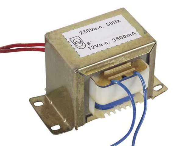
In most simple rectification techniques stepping down the AC supply voltage to a low AC voltage is first step. A 230/12 V, 500 mA transformer is most commonly used for these purposes.
Rectification
As we have discussed we are building an uncontrolled rectifier circuit thus we require diodes for obtaining the half-wave or full-wave structures.

The series 1N400X (X: 1-7) shown very reliable and accurate performance.
Datasheet shows the individual IMP ratings, for safe purpose 1N4007 is selected as they hardly differ in price.

Smoothening
When we set to hunt-up various electrical elements for the purpose of stabilizing a pulsating voltage, no other candidate other than capacitors seems more worthy. Capacitors are utilized in almost all rectifiers.

A capacitor is a basic circuit element which stores charge and retain its potential when external voltage is removed.
Consider the following circuit:

The capacitor is in series with diode and the circuit is fed by an AC supply. The diode will only conduct in the forward biased condition and will block the current when it is in reversed biased, thus the capacitor will get charged to maximum supply voltage and will remain charged forever.
Now lets us connect a resistive load across the capacitor.
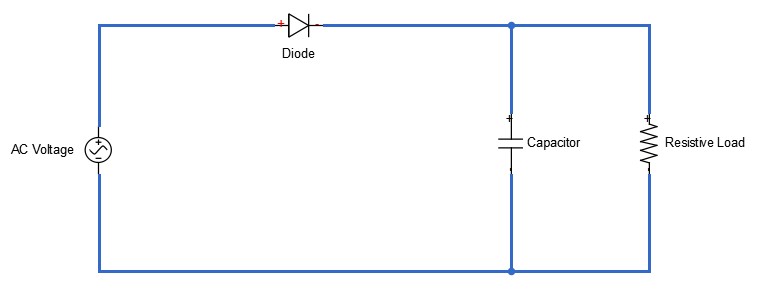
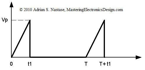
This time when the diode is reverse biased the capacitor will try to get discharged in RC circuit and the voltage across the capacitor will decrease exponentially, whose rate will depend upon the time constant of the RC circuit. The voltage across the capacitor will continue to drop until diode becomes conducting in the forward biased condition and again start charging the capacitor.
Addition of a capacitor will greatly smoothen the voltage waveform across the load and corresponding current, by filling the gaps in voltage waveform.

But to use this theory for smoothening the pulsating DC, we need to look at two things:
- The value of capacitor for the acceptable performance
- The value of current in the circuit for safe operation
WHAT SHOULD THE VALUE OF CAPACITOR?
For optimal operation the drop in voltage ( ) should be minimum as possible. Which is possible only when the time-period of the voltage waveform is much smaller than the time constant of the RC circuit, so that the diode starts conducting after capacitor loses small voltage.
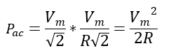
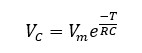
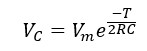
Circuit theory leads us to say that when capacitor begins to discharge the drop in voltage at the terminals of capacitor is given by:
![]()
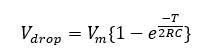
The time for which the capacitor discharges can be approximately taken as T (time-period of source waveform), so the voltage across capacitor drops to:
Thus,
![]()
Evidently, for minimal drop we must have RC >>> T.

For practical purposes, acceptable performance is obtained when:
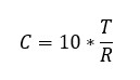
Designing a DC source for LED load
To design any AC to DC converter first thing is we need to consider is the load requirement. We first we have to refer to the datasheets of a white LED, screen shot below (datasheets links at end):

The most crucial parameters to consider are: Continuous forward current = 30 mA; Reverse Voltage = 5 V
So, assuming the current through LED as 20 mA and forward voltage to be 3.5 V for good operation, equivalent resistance came out to be 175 Ω.
We can get the exact voltage across LED if we use transformer of calculated turn ratio. However, only standard transformers are available in market, most viable is the 230/12 V transformer.
So, when 230 V mains is stepped down to 12 V and rectified using single diode the capacitor charges up to 12*1.414 V, which becomes quite high voltage to be used for lighting up a LED.
Resistance in series can be connected for getting required drop across the LED but it dissipates considerable heat.
We can use an Integrated Circuit chip series, IC LM78XX for getting the constant output voltage of XX V for a range of specified input voltage.
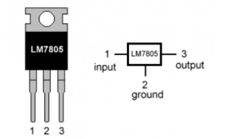
IC LM7805
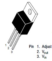
The IC series LM78XX is a three-terminal positive voltage regulator device, with many variant available with output voltages of 5, 6, 8, 9, 10, 12, 15, 18 and 24 V. 7805 is most popular as most of TTL devices has 5 V as operating voltage.
Ease of use, low cost, and self-employed thermal shut-down and safe operating area operating area performance are some great features available with this package.
Pin-out diagrams:
IMP Ratings:
Some of important specification taken for datasheets are:

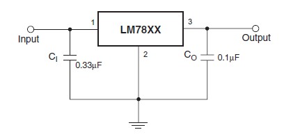
Coupling with the rectifier circuit:
According to the datasheets, the IC should be connected in following manner for optimal operation.
NOTE:
- The value of capacitor can be approximate.
- For obtaining an output voltage of XX V select the LM78XX device and input voltage should be at least 2.5 V greater than XX V. That is a minimum of 7.5 is required for LM7805 to obtain a o/p as 5V.
Also, it is always safe to connect a resistance in series with the LED to check it blowing off.
Using simple circuit theory, we can obtain the value of resistance to limit the current to 20 mA.
The equivalent circuit at load side becomes:

Total current dram is 60 milliamps, which is in safe level as max output current from IC 7805 is 1mA and that of transformer is 500mA.
So, our final circuit become:

Element ratings:
- Transformer: 230/12 V, 500 mA
- Diode: 1N4007
- C = 100 μF
- C1 = 33 μF
- R1 = R2 = R3 = 75 Ω
- C2 = 10 μF
- LED: 5V, 30mA
Using Full-wave Circuit:
As we have seen in previous blog that the performance characteristics are improved significantly by replacing half-wave with full-wave rectifier, better smoothening action is overserved for same capacitors.
Because in this case the time for which the capacitor discharges can be approximately T/2 (half of the time-period of source waveform).

So, the voltage across capacitor drops to:
Thus, drop in voltage here is:
Which is even less than the half-wave case.

Designing a DC source for DC motor:
A DC Motor
A permanent magnet DC motor more or less work in voltage range of 5V-12V, drawing current ~100 mA and rotor RPM in several thousands. The ratings can greatly vary for different motors so individual device ratings should be considered.

It is a two terminal device and direction of rotation changes according to the polarity of supply given.
Typical datasheet:

The battery eliminator we derived for LED can be used satisfactorily to run a DC permanent magnet motor, of specified voltage rating by using LM78XX (XX: 05, 08, 10, 12, 16 etc.), higher capacitor value and transformer of required turn ratio and current ratings.
The voltage obtained is constant and fixed for a given circuit, however voltage control is most desirable property for any motor driving circuit for obtaining variable rotor speed.
Here again comes another wonder of electronics world, the IC LM317.
IC LM317
The Integrated circuit LM317 is a three-terminal, adjustable positive voltage regulator and was designed by American electrical engineer Robert C Dobkin in 1976.
This IC performs functions of its counter-part (LM78XX series) of smoothening fluctuating voltage and is also capable of obtaining a wide range of output voltage for fixed input voltage with allowable load current up to 1.5 A.
Other operational advantages include ease of use, high-performance regulation and self-current limiting capability make it blow-off proof.
Pin-out diagram:
Connections are made considering the three pins to obtain required outcome.
IMP Ratings:
Some of important specification are:

*Note: The device detects only difference in the input and output voltage so as long as the difference is maintained between 3V-40 V and upper limit of output is within limits, input can be anything.
Coupling with the rectifier circuit:
The datasheet provides the circuitry required for obtaining required voltage regulation. Output range 1.25 – 37 V is obtained by varying the potentiometer (R2), according to the equation:
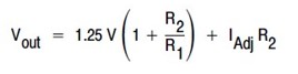
For a given input voltage, max output voltage (i.e. = Vin – 3 V, for minimal voltage differential od 3 V) is obtained for highest value of R2.
So, supposed we require output voltage in range of (XX V-YY V) then input voltage should be at least (YY+3) V and for according to the lower limit XX V, R2 and R1 must be selected, keeping in mind 1.25 is always constant for LM317 for all i/p.

*The capacitors are added to optimize the transient response by filtering out ripples.
Variable Resistor R2:
The job of variable resistance is obtained by a miniature electrical component called the trimmer potentiometers, in short TrimPot.
Trimmer Potentiometer (TrimPot)
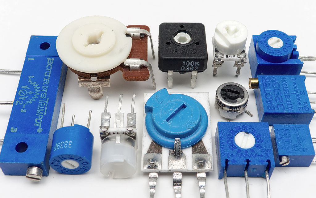
They also come in range of rating from 10 kΩ to 100 kΩ.
Pin-out diagram:

The-three terminal device has its maximum resistance between two fixed terminals and one sliding-terminal fitted with screw is for obtaining variable resistance of around 3% of fixed resistance.
Thus, resistance of 9.7 kΩ – 10 kΩ is obtainable for a 10 kΩ potentiometer.
IMP Ratings:
The device should not be operated at high voltages (< 50 V) and also rotational life is of around 20 cycles.

So, our final circuit becomes:

Element ratings:
We can achieve a fairly good control over the rotor speed (though not very-very precise) by using some standard rated circuit elements.
- Transformer: 230/12 V, 500 mA
- Diode: 1N4007
- C = 2200 μF
- C1 = 33 μF
- R1 = 250 kΩ
- R2 = 10 kΩ
- C2 = 10 μF
- DC Motor: 5V, 100 mA
Here is the massive database link for Rectifier Circuits:
https://drive.google.com/open?id=1YzbjGSF4ZAtZI9q3di0Zhj-uWQlhwUlH
Keep Reading, keep learning
AANTARAK DIVISION
TEAM CEV!!