INTRODUCTION
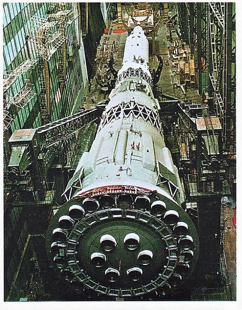
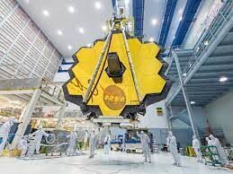
The JWST or Webb is a space telescope which is developed by NASA in collaboration with the European Space Agency and Canadian Space Agency. It will complement the Hubble space telescope and is optimized for the wavelengths in the infrared region. The JWST is 100 times more powerful than it. The diameter of the optical mirror of Webb is 6.5 meters making its collecting area 6.25 times more than Hubble. The Webb consists of 18 hexagonal adjustable mirrors made of gold-plated beryllium with just 48.2 grams of gold, about the same weight as a golf ball. Since the telescope is operating in the infrared region, the temperature around it needs to be very low to prevent the overwhelming of the sensors by the heat from the Sun, the Earth, and the heat emitted by its parts’. To overcome that the special material called Kapton with a coating of aluminum is used such that, one side facing the sun and earth would be around 85 degrees celsius while the other side would be 233 degrees Celsius below zero. Also, the problem of keeping the instrument’s temperature at an optimal level is solved by using liquid helium as the coolant. The telescope is going to have 50 major deployments and 178 release mechanisms for the smooth functioning of the satellite. The Webb was launched on Ariane 5 from Kourou in French Guiana and will take six months to become fully operational and is expected to work for 10 years.
The JWST project was being planned for 30 years and had to face many delays and cost overruns. The first planning was carried out in 1989 whose main mission was to “think about a major mission beyond Hubble”. There were many cost overruns and project delays throughout the making of the telescope. There were also many budget changes throughout the period. The original budget for making the telescope was going to be US$1.6 billion. Which was then estimated to be US$ 5 million by the time construction started in 2008. By 2010, the JWST project almost got shelved due to the huge budgets until November 2011 when Congress reversed the plan to discontinue JWST and set the cap of the funding at US$ 8 billion.
The telescope has been launched to study the early planets and galaxies formed after the Big Bang. The telescope would also help in finding out the formation of new planets and galaxies. The US Congress capped its funding to US$ 6 million.
ORBIT OF THE TELESCOPE
Being an infrared telescope, the position of the telescope in space is crucial for its desired operation. The telescope has to be as far as possible from the sun so that the sun’s infrared ways don’t interfere with the telescope’s instruments as well as not being too far away from the earth to stay in contact with NASA all the time. So NASA decided to put the telescope in Lagrange point 2 of the sun-earth system. So the question arises what is a Lagrange point and what is its importance. Let’s go back and learn how Lagrange and Euler discover these points in space. The Lagrange points are points of equilibrium for small-mass objects under the influence of two massive orbiting bodies. Mathematically, this involves the solution of the restricted three-body problem in which two bodies are very much more massive than the third. These points are named after the French Italian mathematician and astronomer Joseph-Louis Lagrange who discovered the Lagrange points L4 and L5 in 1772 but the first 3 points were discovered by Swiss Mathematician and Astronomer Leonhard Euler in 1772.
Joseph-Louis Lagrange was an Italian mathematician and astronomer. He made significant contributions to the fields of analysis, number theory, and both classical and celestial mechanics. In 1766, on the recommendation of Swiss Leonhard Euler and French d’Alembert, Lagrange succeeded Euler as the director of mathematics at the Prussian Academy of Sciences in Berlin, Prussia, where he stayed for over twenty years, producing volumes of work and winning several prizes of the French Academy of Sciences. Lagrange’s treatise on analytical mechanics written in Berlin and first published in 1788, offered the most comprehensive treatment of classical mechanics since Newton and formed a basis for the development of mathematical physics in the nineteenth century
Lagrange was one of the creators of the calculus of variations, deriving the Euler–Lagrange equations for extrema of functionals. He extended the method to include possible constraints, arriving at the method of Lagrange multipliers. Lagrange invented the method of solving differential equations known as variation of parameters, applied differential calculus to the theory of probabilities, and worked on solutions for algebraic equations. In calculus, Lagrange developed a novel approach to interpolation and Taylor theorem. He studied the three-body problem for the Earth, Sun, and Moon (1764) and the movement of Jupiter’s satellites (1766), and in 1772 found the special-case solutions to this problem that yield what are now known as Lagrangian points. Lagrange is best known for transforming Newtonian mechanics into a branch of analysis, Lagrangian mechanics, and presented the mechanical “principles” as simple results of the variational calculus.
Normally, the two massive bodies exert an unbalanced gravitational force at a point, altering the orbit of whatever is at that point. At the Lagrange points, the gravitational forces of the two large bodies and the centrifugal force balance each other. This can make Lagrange points an excellent location for satellites, as few orbit corrections are needed to maintain the desired orbit. L1, L2, and L3 are on the line through the centers of the two large bodies, while L4 and L5 each act as the third vertex of an equilateral triangle formed with the centers of the two large bodies. L4 and L5 are stable, which implies that objects can orbit around them in a rotating coordinate system tied to the two large bodies. Now the magic of L2 point is that it is behind the earth and the sun thus if we want to view the night sky without the earth’s intervention when can do it from this point and since it is in the Lagrange point it is orbiting in the same speed as the earth so it can be in continuous communication with the earth through the Deep Space Network using 3 large antennas on the ground located in Australia, Spain, and the USA and can uplink command sequence and downlink data up to twice per day and use minimal fuel to stay in the orbit thus increasing the lifespan of the mission.
The telescope is going to be 1.5 million km away from the earth and will circle about the L2 point in a halo orbit, which will be inclined with respect to the ecliptic, have a radius of approximately 800,000 km, and take about half a year to complete. Since L2 is just an equilibrium point with no gravitational pull, a halo orbit is not an orbit in the usual sense: the spacecraft is actually in orbit around the Sun, and the halo orbit can be thought of as controlled drifting to remain in the vicinity of the L2 point. It will take the telescope roughly 30 days to reach the start of its orbit in L2.
Unlike the Hubble telescope which can be easily serviced in case of damage, the James Webb Space Telescope cannot be repaired/serviced due to its significant distance(1.5 million km) from earth even more than the most distance traveled by the astronauts during the Apollo 13 mission in which they traveled to the far side of the moon which is approximately 400,000 km from earth. Therefore this is one of the riskiest missions in human history with 344 single points failure could lead to the end of the mission and years of research and hard work of thousands of scientists down the drain.
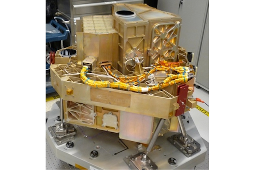
PARTS OF TELESCOPE
NIRCam:
INTRODUCTION:
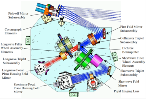
NIRCam (Near-infrared camera) is an instrument that is part of the James Webb Space Telescope. The main tasks of this instrument include first as an imager from 0.6 to 5-micron wavelength, and second is as a wavefront sensor to keep 18 section mirrors functioning as one. It is an infrared camera with ten mercury-cadmium-telluride (HgCdTe) detector arrays, and each array has an array of 2048×2048 pixels. Also, NIRCam has coronagraphs which are normally used for collecting data on exoplanets near stars. NIRCam should be able to observe as faint as magnitude +29 with a 10000-second exposure (about 2.8 hours). It makes these observations in light from 0.6 (600 nm) to 5 microns (5000 nm) wavelength.
COMPONENTS:
The main components of NirCam are coronagraph, first fold mirror, collimator Pupil imaging lens, senses, dichroic beam splitter, Longwave focal plane, Shortwave filter wheel assembly, Shortwave camera lens group, Shortwave fold mirror, Shortwave focal plane
DESIGN:
NIRCam is designed by the University of Arizona, company Lockheed Martin, and Teledyne Technologies, in cooperation with the U.S. Space Agency, NASA. NIRCam has been designed to be efficient for surveying through the use of dichroic.
WORKING:
The Near Infrared Camera (NIRCam) is Webb’s primary imager that will cover the infrared wavelength range of 0.6 to 5 microns. NIRCam will detect light from the earliest stars and galaxies in the process of formation, the population of stars in nearby galaxies, as well as young stars in the Milky Way and Kuiper Belt objects. NIRCam is equipped with coronagraphs, instruments that allow astronomers to take pictures of very faint objects around a central bright object, like stellar systems. NIRCam’s coronagraph works by blocking a brighter object’s light, making it possible to view the dimmer object nearby – just like shielding the sun from your eyes with an upraised hand can allow you to focus on the view in front of you. With the coronagraphs, astronomers hope to determine the characteristics of planets orbiting nearby stars.
NIRSpec:
INTRODUCTION:
The NIRSpec (near-infrared spectrograph) is one of the four instruments which is flown with the James Webb space telescope. The main purpose of developing the NIRSpec is to get more information about the origins of the universe by observing the infrared light from the first stars and galaxies. This will also help in allowing us to look further back in time and will study the so-called Dark Ages during which the universe was opaque, about 150 to 800 million years after the Big Bang.
COMPONENTS:
Coupling optics, fore optics TMA, calibration mirror 1 and2, calibration assembly, filter wheel assembly, refocus mechanism assembly, micro shutter assembly, integral field unit, fold mirror, collimator TMA, grating wheel assembly, camera TMA, focal plane assembly, SIDECAR ASIC, optical assembly internal harness.
MICROSHUTTER:
Micro shutters are tiny windows with shutters that each measure 100 by 200 microns, or about the size of a bundle of only a few human hairs. The micro shutter device can select many objects in one viewing for simultaneous high-resolution observation which means much more scientific investigation can be done in less time. The micro shutter device is that it can select many objects in one viewing for simultaneous observation and it is programmable for any field of objects in the sky. The micro shutter is a key component in the NIRSpec instrument. Micro shutter is also known as arrays of tiny windows.

FINE GUIDANCE SENSOR:
INTRODUCTION:
The fine guidance sensor (FGS) is a typical instrument board on a James Webb space telescope, this provides high precision pointing information as input to the telescope’s attitude control systems. FGS provides input for the observatory’s attitude control system (ACS). During on-orbit commissioning of the JWST, the FGS will also provide pointing error signals during activities to achieve alignment and phasing of the segments of the deployable primary mirror.
COMPONENTS:
THE FGS don’t have that much complex structure. so the following are the main components of FGS:- The large structure housing a collection of mirrors, lenses, servos, prisms, beam-splitters, photomultiplier tubes.
WORKING:
The FGS has mainly three functions in which this instrument was planted in our telescope:
1) TO obtain images for target acquisition. Full-frame images are used to identify star fields by correlating the observed brightness and position of sources with the properties of cataloged objects selected by the observation planning software
2) Acquire pre-selected guide stars. During acquisition, a guide star is first centered in an 8 × 8 pixel window.
3) Provide the ACS with centroid measurements of the guide stars at a rate of 16 times per second.
DESIGN:

MIRI:
The mid-infrared instrument is used in the detection process of the James Webb Space Telescope. Uses camera as well as a spectroscope, in detection helps in detection from 5 microns to 28 microns of radiation to observe such a large range of wavelength we use Detectors made up of Germanium doped with arsenic these detectors are termed as Focus plane modules and have a resolution about 1024 X 1024 pixels. The MIRI system needs to be cooler than other instruments to measure such a long wavelength range and provided with cryocoolers which consist of two elements i.e. pulse tube precooler and Joule Thompson loop heat exchanger to cool down the MIRI to 7 K while operating. Consists of two types of spectroscopes
Medium Resolution Spectroscope- it is the main spectroscope that uses Dichroic and Gratings.
Low-resolution Spectroscope- it helps in slitless and long-slit spectroscopy with the help of double prisms to get the spectrum from range 5 to 12 micrometer. Uses Germanium and zinc sulfide prisms to get the dispersion of light.


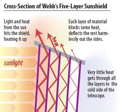
SUNSHIELD:
To observe faint heat signals the JWST must need to be extremely cold to detect those faint signals. Sunshield helps in protecting the telescope from heat and light from the sun as well as the heat of the observatory also helps in maintaining a thermally stable environment and helps in cooling to 50K.
The sun shield is made up of a material named Kapton which is coated with aluminum and the two hottest plates facing the sun also have silicone doping to reflect heat and light from the sun. have high resistance and are stable in a wide range of temperatures.
The number of plates and shape of plates play an important role in the shielding process. Five layers are used to protect the telescope and the vacuum between each sheet acts as an insulating medium to heat. Each layer is incredibly thin and the layers are curved from the center.
Some quick facts regarding the JWST:
The Webb’s primary mirror is 6.5 meters wide. A mirror this large hasn’t been launched in space before.
It will help humans to understand the dark age before the time when the first galaxies were formed.
As of now, the JWST is fully deployed in space and is in its cooldown to let its apparatus work at an optimum level. So let’s hold our breaths for the wonderful and exciting discoveries that are yet to come.