India successfully launched its third lunar exploration mission, Chandrayaan-3, on Friday, July 14, 2023. The mission is expected to soft land on the surface of the moon on August 23-24, making India the fourth country to achieve this feat.
The Chandrayaan-3 spacecraft consists of a lander, a rover, and an orbiter. The lander will carry the rover, which will be deployed on the lunar surface to conduct scientific experiments. The orbiter will remain in lunar orbit to study the moon’s surface and atmosphere.
The Chandrayaan-3 mission is a follow-up to the Chandrayaan-2 mission, which failed to soft land on the moon in 2019. The Indian Space Research Organisation (ISRO) has made several improvements to the lander for the Chandrayaan-3 mission, including stronger legs, a more powerful engine, and a new guidance system.
The successful launch of Chandrayaan-3 is a major milestone for India’s space program. It demonstrates India’s growing capabilities in space exploration and its commitment to scientific research.
What are the scientific goals of Chandrayaan-3?
The Chandrayaan-3 mission has a number of scientific goals, including:
Studying the composition and structure of the lunar surface.
Exploring the moon’s water resources
Investigating the moon’s potential for future human exploration
The rover will be equipped with a variety of instruments to conduct these studies, including a spectrometer, a camera, and a drill. The orbiter will also carry a number of instruments, including a radar and a magnetometer.
What is the significance of Chandrayaan-3?
The Chandrayaan-3 mission is significant for a number of reasons. First, it will make India the fourth country to soft land on the moon. Second, it will help to further our understanding of the moon’s composition and structure. Third, it will explore the moon’s potential for future human exploration.
The success of Chandrayaan-3 would be a major achievement for India’s space program and would help to put India at the forefront of lunar exploration. It would also inspire the next generation of scientists and engineers to pursue careers in space exploration.
What is the next step for Chandrayaan-3?
The Chandrayaan-3 spacecraft will now enter a lunar transfer orbit. It will then orbit the moon for several weeks before attempting to soft land on the surface. The landing is scheduled to take place on August 23-24, 2023.
If the landing is successful, the rover will be deployed on the lunar surface to conduct scientific experiments. The orbiter will remain in lunar orbit to study the moon’s surface and atmosphere.
The Chandrayaan-3 mission is a major undertaking, but it has the potential to make significant contributions to our understanding of the moon. ISRO is confident that the mission will be a success, and they are excited to see what the future holds for lunar exploration.
Time travel is commonly defined by David Lewis’ definition: An object time travels if and only if the difference between its departure and arrival times as measured in the surrounding world does not equal the duration of the journey undergone by the object.
People ask is time travel a philosophical structure or hypothetical or mathematically shown? The answer is that it is the combination of them all!!
Can we travel in time?
Yes, we can! Even we are traveling in time at a steady rate of one second per second or one hour per hour. Most commonly we are taught that there are only three dimensions and there is no similarity in traveling between 2 spatial dimensions. But according to Einstein’s theory of relativity we live in a four-dimensional continuum i.e. space-time in which space and time are interchangeable.
Many of you may have heard about the novel “The Time Machine” by H.G. Wells published in 1895. One of the earliest works in this genre, where Well talked about the concept of time travel by using a device or machine to travel purposely backward or forward in time.
In today’s date, Wikipedia lists over 400 titles in the category, ‘Movies about time travel’ In documentaries like “Back to future”, “Doctor Who”, and “Star Trek” characters climb into some wild vehicle to blast into the past or spin into the future.
Many of us are fascinated by the idea of changing the past or looking into the future, but no person has ever demonstrated the kind of back-and-forth time travel depicted in science fiction. Neither of them has proposed any method of sending a person through time without destroying them.
But that also doesn’t mean that time travel is not happening. We know that according to Einstein’s theory of relativity, the faster we move the slower we experience time. A clock on a jet airplane will run slightly behind the clock on the ground.
But what we don’t know is that we are using the fundamentals of time travel in many day-to-day activities.
Time Travel Applications
We use GPS technology to search for varied locations across the globe. NASA also uses high accuracy version of GPS to keep track of where satellites are in space.
To our surprise, this whole system relies on time travel calculations. We and the satellites are traveling into the future at very slightly different rates.GPS satellites orbit around Earth very quickly at about 8,700 milesper hour. This slows down GPS satellite clocks by a small fraction of a second (as demonstrated in 2 clocks example above).
However, the satellites are also orbiting Earth about 12,550 miles above the surface. This actually speedsup GPS satellite clocks by a slighter larger fraction of a second.
Here’s how: Gravity is much weaker at the height where these satellites orbit.
Einstein’s theory also says that gravity slows down the passage of time. So the clocks will run at a faster pace where the gravity is comparatively less.
The combined result is that the clocks on GPS satellites experience time at a rate slightly faster than 1 second per second. Luckily, scientists can use math to correct these differences in time.
If all these corrections are being ignored, GPS maps might think your home is nowhere near where it actually is!
Time travel into future
If you want to advance through the years a little faster than the next person, you’ll need to exploit space-time. As we see above Global positioning satellites (GPS) pull this off every day, accruing an extra third-of-a-billionth of a second daily.
You wouldn’t be able to notice minute changes in the flow of time, but a sufficiently massive object would make a huge difference — say, like the supermassive black hole at the center of our galaxy. Here, the mass of 4 million suns exists as a single, infinitely dense point, known as a “Singularity”. Circle this black hole for a while (without falling in) and you’d experience time at half the Earth rate. In other words, due to time dilation you’d round out a five-year journey to discover an entire decade had passed on Earth.
Quite a similar thing was shown in movie the “Interstellar” directed by Christopher Nolan.
In the movie, the crew spends a few hours on a planet orbiting a supermassive black hole, but because of time dilation, observers on Earth experience those hours as a matter of decades.
Thinking in this way we are traveling into the future. But what about the past? Could the fastest starship imaginable turn back the clock?
Time Travel into the past(Changing history!)
A big question in all of our minds. Can we change our history? Can engineers take their decision back of pursuing engineering?
A glance into the night sky should supply an answer. The Milky Way galaxy is roughly 100,000 light-years wide, so the light from its more distant stars can take thousands upon thousands of years to reach Earth. Glimpsethat light, and you’re essentially looking back in time.
But can we do better than this?
There’s nothing in Einstein’s theory that precludes time travel into the past, but the very premise of pushing a button and going back to yesterday violates the law of causality. One event happens in our universe, and it leads to yet another in an endless one-way string of events. In every instance, the cause occurs before the effect.
What happens if you go back in time and kill your parents before you are born. How can you be born?
To travel back in time, some scientists proposed the idea of traveling at a speed greater than the speed of light. After all, if the time slows down for the object approaching the speed of light, then exceeding that limit might cause the time to flow backward. But as an object nears the speed of light its relative mass increases until it becomes infinite at light speed.
Accelerating an infinite mass any faster than that is impossible. Maybe that’s the reason we can’t move backward in time.
Conclusion
We may reach to the conclusion that time travel is possible but probably not in the way we see it in science fiction and movies. There are still many cards unturned and a lot more to know about this vast topic. Hopefully, this blog gave you a headstart!
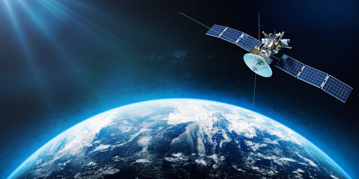
The curiosity about what was there 13.5 billion years ago and the search for the habitable planets might end. On 25th December 2021, NASA launched their massive 10 billion dollar endeavor, which will help humans look for what was there and what surprises the universe holds for us. The expensive James Webb Space telescope, simply called Webb, is named after James E. Webb, who served as the second administrator of NASA during the 60s and oversaw U.S. crewed missions throughout the Mercury and Gemini programs.
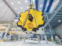
The JWST or Webb is a space telescope which is developed by NASA in collaboration with the European Space Agency and Canadian Space Agency. It will complement the Hubble space telescope and is optimized for the wavelengths in the infrared region. The JWST is 100 times more powerful than it. The diameter of the optical mirror of Webb is 6.5 meters making its collecting area 6.25 times more than Hubble. The Webb consists of 18 hexagonal adjustable mirrors made of gold-plated beryllium with just 48.2 grams of gold, about the same weight as a golf ball. Since the telescope is operating in the infrared region, the temperature around it needs to be very low to prevent the overwhelming of the sensors by the heat from the Sun, the Earth, and the heat emitted by its parts’. To overcome that the special material called Kapton with a coating of aluminum is used such that, one side facing the sun and earth would be around 85 degrees celsius while the other side would be 233 degrees Celsius below zero. Also, the problem of keeping the instrument’s temperature at an optimal level is solved by using liquid helium as the coolant. The telescope is going to have 50 major deployments and 178 release mechanisms for the smooth functioning of the satellite. The Webb was launched on Ariane 5 from Kourou in French Guiana and will take six months to become fully operational and is expected to work for 10 years.
The JWST project was being planned for 30 years and had to face many delays and cost overruns. The first planning was carried out in 1989 whose main mission was to “think about a major mission beyond Hubble”. There were many cost overruns and project delays throughout the making of the telescope. There were also many budget changes throughout the period. The original budget for making the telescope was going to be US$1.6 billion. Which was then estimated to be US$ 5 million by the time construction started in 2008. By 2010, the JWST project almost got shelved due to the huge budgets until November 2011 when Congress reversed the plan to discontinue JWST and set the cap of the funding at US$ 8 billion.
The telescope has been launched to study the early planets and galaxies formed after the Big Bang. The telescope would also help in finding out the formation of new planets and galaxies. The US Congress capped its funding to US$ 6 million.
ORBIT OF THE TELESCOPE
Being an infrared telescope, the position of the telescope in space is crucial for its desired operation. The telescope has to be as far as possible from the sun so that the sun’s infrared ways don’t interfere with the telescope’s instruments as well as not being too far away from the earth to stay in contact with NASA all the time. So NASA decided to put the telescope in Lagrange point 2 of the sun-earth system. So the question arises what is a Lagrange point and what is its importance. Let’s go back and learn how Lagrange and Euler discover these points in space. The Lagrange points are points of equilibrium for small-mass objects under the influence of two massive orbiting bodies. Mathematically, this involves the solution of the restricted three-body problem in which two bodies are very much more massive than the third. These points are named after the French Italian mathematician and astronomer Joseph-Louis Lagrange who discovered the Lagrange points L4 and L5 in 1772 but the first 3 points were discovered by Swiss Mathematician and Astronomer Leonhard Euler in 1772.
Joseph-Louis Lagrange was an Italianmathematician and astronomer. He made significant contributions to the fields of analysis, number theory, and both classical and celestial mechanics. In 1766, on the recommendation of SwissLeonhard Euler and French d’Alembert, Lagrange succeeded Euler as the director of mathematics at the Prussian Academy of Sciences in Berlin, Prussia, where he stayed for over twenty years, producing volumes of work and winning several prizes of the French Academy of Sciences. Lagrange’s treatise on analytical mechanics written in Berlin and first published in 1788, offered the most comprehensive treatment of classical mechanics since Newton and formed a basis for the development of mathematical physics in the nineteenth century
Lagrange was one of the creators of the calculus of variations, deriving the Euler–Lagrange equations for extrema of functionals. He extended the method to include possible constraints, arriving at the method ofLagrange multipliers. Lagrange invented the method of solving differential equations known as variation of parameters, applied differential calculus to the theory of probabilities, and worked on solutions for algebraic equations. In calculus, Lagrange developed a novel approach to interpolation and Taylor theorem. He studied the three-body problem for the Earth, Sun, and Moon (1764) and the movement of Jupiter’s satellites (1766), and in 1772 found the special-case solutions to this problem that yield what are now known as Lagrangian points. Lagrange is best known for transforming Newtonian mechanics into a branch of analysis,Lagrangian mechanics, and presented the mechanical “principles” as simple results of the variational calculus.
Normally, the two massive bodies exert an unbalanced gravitational force at a point, altering the orbit of whatever is at that point. At the Lagrange points, thegravitational forces of the two large bodies and the centrifugal force balance each other. This can make Lagrange points an excellent location for satellites, as few orbit corrections are needed to maintain the desired orbit. L1, L2, and L3 are on the line through the centers of the two large bodies, while L4 and L5 each act as the third vertex of an equilateral triangle formed with the centers of the two large bodies. L4 and L5 are stable, which implies that objects can orbit around them in a rotating coordinate system tied to the two large bodies. Now the magic of L2 point is that it is behind the earth and the sun thus if we want to view the night sky without the earth’s intervention when can do it from this point and since it is in the Lagrange point it is orbiting in the same speed as the earth so it can be in continuous communication with the earth through the Deep Space Network using 3 large antennas on the ground located in Australia, Spain, and the USA and can uplink command sequence and downlink data up to twice per day and use minimal fuel to stay in the orbit thus increasing the lifespan of the mission.
The telescope is going to be 1.5 million km away from the earth and will circle about theL2 point in a halo orbit, which will be inclined with respect to the ecliptic, have a radius of approximately 800,000 km, and take about half a year to complete. Since L2 is just an equilibrium point with no gravitational pull, a halo orbit is not an orbit in the usual sense: the spacecraft is actually in orbit around the Sun, and the halo orbit can be thought of as controlled drifting to remain in the vicinity of the L2 point. It will take the telescope roughly 30 days to reach the start of its orbit in L2.
Unlike the Hubble telescope which can be easily serviced in case of damage, the James Webb Space Telescope cannot be repaired/serviced due to its significant distance(1.5 million km) from earth even more than the most distance traveled by the astronauts during the Apollo 13 mission in which they traveled to the far side of the moon which is approximately 400,000 km from earth. Therefore this is one of the riskiest missions in human history with 344 single points failure could lead to the end of the mission and years of research and hard work of thousands of scientists down the drain.
PARTS OF TELESCOPE
NIRCam:
INTRODUCTION:
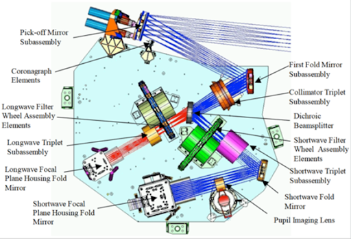
NIRCam (Near-infrared camera) is an instrument that is part of the James Webb Space Telescope. The main tasks of this instrument include first as an imager from 0.6 to 5-micron wavelength, and second is as a wavefront sensor to keep 18 section mirrors functioning as one. It is an infrared camera with ten mercury-cadmium-telluride (HgCdTe) detector arrays, and each array has an array of 2048×2048 pixels. Also, NIRCam has coronagraphs which are normally used for collecting data on exoplanets near stars. NIRCam should be able to observe as faint as magnitude +29 with a 10000-second exposure (about 2.8 hours). It makes these observations in light from 0.6 (600 nm) to 5 microns (5000 nm) wavelength.
COMPONENTS:
The main components of NirCam are coronagraph, first fold mirror, collimator Pupil imaging lens, senses, dichroic beam splitter, Longwave focal plane, Shortwave filter wheel assembly, Shortwave camera lens group, Shortwave fold mirror, Shortwave focal plane
DESIGN:
NIRCam is designed by the University of Arizona, company Lockheed Martin, and Teledyne Technologies, in cooperation with the U.S. Space Agency, NASA. NIRCam has been designed to be efficient for surveying through the use of dichroic.
WORKING:
The Near Infrared Camera (NIRCam) is Webb’s primary imager that will cover the infrared wavelength range of 0.6 to 5 microns. NIRCam will detect light from the earliest stars and galaxies in the process of formation, the population of stars in nearby galaxies, as well as young stars in the Milky Way and Kuiper Belt objects. NIRCam is equipped with coronagraphs, instruments that allow astronomers to take pictures of very faint objects around a central bright object, like stellar systems. NIRCam’s coronagraph works by blocking a brighter object’s light, making it possible to view the dimmer object nearby – just like shielding the sun from your eyes with an upraised hand can allow you to focus on the view in front of you. With the coronagraphs, astronomers hope to determine the characteristics of planets orbiting nearby stars.
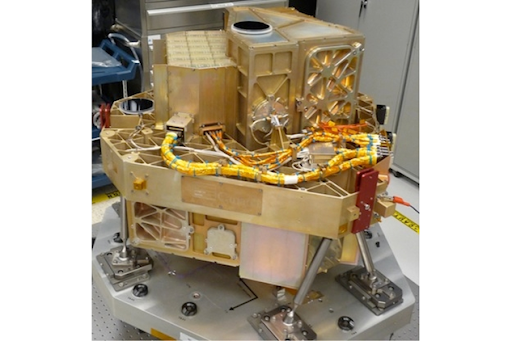
NIRSpec:
INTRODUCTION:
The NIRSpec (near-infrared spectrograph) is one of the four instruments which is flown with the James Webb space telescope. The main purpose of developing the NIRSpec is to get more information about the origins of the universe by observing the infrared light from the first stars and galaxies. This will also help in allowing us to look further back in time and will study the so-called Dark Ages during which the universe was opaque, about 150 to 800 million years after the Big Bang.
Micro shutters are tiny windows with shutters that each measure 100 by 200 microns, or about the size of a bundle of only a few human hairs. The micro shutter device can select many objects in one viewing for simultaneous high-resolution observation which means much more scientific investigation can be done in less time. The micro shutter device is that it can select many objects in one viewing for simultaneous observation and it is programmable for any field of objects in the sky. The micro shutter is a key component in the NIRSpec instrument. Micro shutter is also known as arrays of tiny windows.
FINE GUIDANCE SENSOR:
INTRODUCTION:
The fine guidance sensor (FGS) is a typical instrument board on a James Webb space telescope, this provides high precision pointing information as input to the telescope’s attitude control systems.FGS provides input for the observatory’s attitude control system (ACS). During on-orbit commissioning of the JWST, the FGS will also provide pointing error signals during activities to achieve alignment and phasing of the segments of the deployable primary mirror.
COMPONENTS:
THE FGS don’t have that much complex structure. so the following are the main components of FGS:- The large structure housing a collection of mirrors, lenses, servos, prisms, beam-splitters, photomultiplier tubes.
WORKING:
The FGS has mainly three functions in which this instrument was planted in our telescope:
1)TO obtain images for target acquisition. Full-frame images are used to identify star fields by correlating the observed brightness and position of sources with the properties of cataloged objects selected by the observation planning software
2)Acquire pre-selected guide stars. During acquisition, a guide star is first centered in an 8 × 8 pixel window.
3) Provide the ACS with centroid measurements of the guide stars at a rate of 16 times per second.
DESIGN:
MIRI:
The mid-infrared instrument is used in the detection process of the James Webb Space Telescope. Uses camera as well as a spectroscope, in detection helps in detection from 5 microns to 28 microns of radiation to observe such a large range of wavelength we use Detectors made up of Germanium doped with arsenic these detectors are termed as Focus plane modules and have a resolution about 1024 X 1024 pixels. The MIRI system needs to be cooler than other instruments to measure such a long wavelength range and provided with cryocoolers which consist of two elements i.e. pulse tube precooler and Joule Thompson loop heat exchanger to cool down the MIRI to 7 K while operating. Consists of two types of spectroscopes
Medium Resolution Spectroscope- it is the main spectroscope that uses Dichroic and Gratings.
Low-resolution Spectroscope- it helps in slitless and long-slit spectroscopy with the help of double prisms to get the spectrum from range 5 to 12 micrometer. Uses Germanium and zinc sulfide prisms to get the dispersion of light.
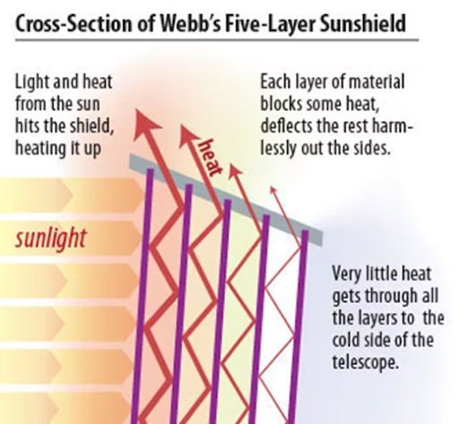
SUNSHIELD:
To observe faint heat signals the JWST must need to be extremely cold to detect those faint signals. Sunshield helps in protecting the telescope from heat and light from the sun as well as the heat of the observatory also helps in maintaining a thermally stable environment and helps in cooling to 50K.
The sun shield is made up of a material named Kapton which is coated with aluminum and the two hottest plates facing the sun also have silicone doping to reflect heat and light from the sun. have high resistance and are stable in a wide range of temperatures.
The number of plates and shape of plates play an important role in the shielding process. Five layers are used to protect the telescope and the vacuum between each sheet acts as an insulating medium to heat. Each layer is incredibly thin and the layers are curved from the center.
Some quick facts regarding the JWST:
The Webb’s primary mirror is 6.5 meters wide. A mirror this large hasn’t been launched in space before.
It will help humans to understand the dark age before the time when the first galaxies were formed.
As of now, the JWST is fully deployed in space and is in its cooldown to let its apparatus work at an optimum level. So let’s hold our breaths for the wonderful and exciting discoveries that are yet to come.
Reading Time: 8minutesSince the past few days, there has been a buzz around everywhere, Not only in India but the world around. For some, it’s a challenge for others its pride. So, what’s it all about? You are right, for every Indian, it’s a moment of great pride and honour to launch our next moon mission Chandrayaan-2. But before discussing it, let us brush up our knowledge on the whole series of Indian Lunar Mission “THE CHANDRAYAAN PROGRAMME”.
Why Moon?
Since childhood we have been witnessing the white round moon ‘our chandamama’ grow big and small daily. Many of us had dreamt to go to the moon and play with the stars. But growing up we realise that the moon is not our neighbour next window but yes somewhere closer to our childhood. So, let’s fulfil our childhood dream and fasten our seatbelts to go to moooooooon!!!!!!
Being Earth’s only natural satellite moon provides the best linkage to Earth’s early history. It had witnessed each and every moment of our existence. It offers a great historical record of the inner Solar system environment. Though there are a few explained models, the origin of the Moon still needs further explanations. Extensive mapping of the lunar surface, to study variations in lunar surface composition is essential to trace back the origin and evolution of the Moon and this can further be helpful to study the origin and evolution of solar system and universe.
Chandrayaan programme is India’s Lunar Exploration Program. It is a series of outer space missions under the Indian Space Research Organisation (ISRO). The program consists of different parts which are a lunar orbiter, impactor, future lunar lander and rover spacecraft.
The Chandrayaan project was announced on 15 August 2003 by then Prime Minister Atal Bihari Vajpayee. This program was launched to boost Indian space programs and embarking India’s name in history.
Chandrayaan is a multi-phase mission-
The first phase includes the launch of CHANDRAYAAN – 1 which was a lunar orbiter.
The second phase includes the launch of soft lander/Rover Vikram and Pragyan as CHANDRAYAAN-2.
The third phase is planned to be an in-situ sampling collection expected in 2024 as CHANDRAYAAN-3.
CHANDRAYAAN-1
Launched on 22 October 2008 Chandrayaan 1 was the first milestone for Indian lunar programme. It was launched by ISRO from Satish Dhawan Space Centre, Sriharikota. It was unique in its sense that it was researched and developed fully in India by Indian scientists and researchers. The vehicle was inserted in the lunar orbit on 8 November 2008. On 14 November 2008, the Moon Impact Probe (MIP) separated from the Chandrayaan orbiter at 14:36 UTC and struck the south pole in a controlled manner, making India the fourth country in the world to place its flag on the Moon. The probe hit near the crater Shackleton at 15:01 UTC (20:31 IST). The location of impact of the probe was named as Jawahar Point.
The estimated cost of the project was around ₹386 crore (USD 56 million). Along with other objectives, the area around polar regions was of high interest as it may contain ice and may result in the discovery of water on the moon. The lunar mission in total carried 11 payloads, five of them were ISRO payloads and six payloads from other space agencies including NASA, ESA, and the Bulgarian Aerospace Agency. The payloads form these agencies were carried free of cost.
The stated objectives of this mission were: –
perform high-resolution remote sensing of the moon in – visible, near-infrared (NIR), low energy X-rays and high-energy X-ray regions
survey the lunar surface to produce a complete map of its chemical characteristics
prepare a three-dimensional atlas of both near and far side of the moon
conduct chemical and mineralogical mapping of the entire lunar surface for distribution of mineral and chemical elements such as Magnesium, Aluminium, Silicon, Calcium, Iron and Titanium and also high atomic number elements such as Radon, Uranium & Thorium.
test the impact of a sub-satellite (Moon Impact Probe – MIP) on the surface of the Moon as a forerunner for future soft-landing missions
The mission carried five scientific payloads from India, according to the ISRO these were:
Terrain Mapping Camera (TMC), which provided a high-resolution map of the moon.
Hyper Spectral Imager (HySI), which performed the mineralogical mapping.
Lunar Laser Ranging Instrument (LLRI), which returned information about the moon’s topography (height of certain features).
High Energy X-ray Spectrometer (HEX), which examined radioactive elements on the surface.
Moon Impact Probe (MIP), which was intentionally crashed into the moon’s south pole. Its impact helped Chandrayaan-1 in its search for lunar water.
What happened when: Timeline of Chandrayaan – 1
15th August 2003: Chandrayaan programme was announced by Prime Minister Atal Bihari Vajpayee
22nd October 2008: Chandrayaan-1 takes off from the Satish Dhawan Space Centre, Sriharikota
8th November 2008: Chandrayaan-1 enters the Lunar Transfer Trajectory
14th November 2008: The Moon Impact Probe ejects from Chandrayaan 1 and crashes near the lunar South Pole — confirms the presence of water molecules on Moon’s surface
28th August 2009: Chandrayaan-1 programme ends
What we Achieved from this mission?
1. Water on the Moon
On 18 Nov 2008, the Moon Impact Probe was released from Chandrayaan at a height of 100km. During its descent to the moon surface, Chandra’s Altitudinal Composition Explorer (CHACE) recorded evidence of water on the moon. This discovery was later confirmed by JPL-Brown University payload – Moon Mineralogy Mapper (M3), a payload by NASA. M3 detected spectral lines near the wavelengths in the range of 2.8 – 3.0 microns, a property attributed to water and Hydroxyl ions. It is believed that the formation of Hydroxyl ions and water molecules on the lunar surface is an ongoing process.
According to European Space Agency (ESA) scientists, the lunar regolith (a loose collection of irregular dust grains making up the Moon’s surface) absorbs hydrogen nuclei from solar winds. The hydrogen nuclei and oxygen present in the dust grains interact and are expected to produce hydroxyl (HO−) and water (H2O).
2. Imaging of North and South Pole of the Moon
This was done by two different devices namely –
Terrain Mapping Camera (TMC)
Hyper Spectral Images (HySI)
3. 3-D profile of Clavius (one of the largest craters on moon)
Lunar Laser Ranging Instrument (LLRI) mapped Clavius, the third largest crater on the near side of the moon, a feature observable with little aid and even with the naked eye.
The mineral content on the lunar surface was mapped with the Moon Mineralogy Mapper (M3), a NASA instrument on board of the orbiter. The Oriental Basin region of the Moon was mapped, and it indicates an abundance of iron-bearing minerals.
Chandrayaan-1 Imaging X-ray Spectrometer: The purple arrow shows the spacecraft track over the Moon; the different coloured rectangles show the area of the Moon that C1XS was looking at. The yellow and red areas show strong X-ray signals that correspond to Silicon, Aluminium and Magnesium, at the right hand end the green/turquoise area shows X-rays due to Calcium.
4. Mapping of various minerals
The mineral content on the lunar surface was mapped with the Moon Mineralogy Mapper (M3), a NASA instrument on board of the orbiter. The Oriental Basin region of the Moon was mapped, and it indicates an abundance of iron-bearing minerals.
Chandrayaan-1 Imaging X-ray Spectrometer: The purple arrow shows the spacecraft track over the Moon; the different coloured rectangles show the area of the Moon that C1XS was looking at. The yellow and red areas show strong X-ray signals that correspond to Silicon, Aluminium and Magnesium, at the right hand end the green/turquoise area shows X-rays due to Calcium.
5. Mapping of Apollo landing sites
In January 2009, ISRO announced the completion of the mapping of the Apollo Moon missions landing sites by the orbiter. Six of the mapped sites included landing sites of Apollo 12, 14 and 16 (can be referred in the previous image).
6. Radiation environment around the Moon
Radiation Dose Monitor or RADOM-7 (a payload from the Bulgarian Academy of Sciences) examined the radiation environment around the moon.
End of the mission
The mission was launched on 22 October 2008 and was expected to operate for two years. However, around 20:00 UTC (11:00 IST) on 28 August 2009 communication with the spacecraft was suddenly lost. Chandrayaan-1 made 3,400 orbits of the moon and continued transmitting data until 28 August 2009, when controllers permanently lost communication with the spacecraft. The probe had operated for 312 days. Earlier it was expected that the craft crashed into the lunar surface but in 2016 it was found still to be in the orbit. Although the mission lasted less than its expected duration, but a team of scientists from ISRO stated the mission to be successful as it had achieved 95% of its desired objectives in this time duration.
Chandrayaan 1 was a major success not only for Indian fraternity but also to Space Science as a whole. It expanded India’s footprint in space and proposed a whole together new dimensions to space. Chandrayaan-1 was lauded with a number of awards and recognitions as below –
The American Institute of Aeronautics and Astronautics (AIAA) has selected ISRO’s Chandrayaan-1 mission as one of the recipients of its annual AIAA SPACE 2009 awards.
The International Lunar Exploration Working Group awarded the Chandrayaan-1 team the International Co-operation Award in 2008.
US-based National Space Society awarded ISRO the 2009 Space Pioneer Award in the science and engineering category.
So, this was the first Lunar mission of India, tricolour for the first time fluttered on the moon’s surface. Stay tuned for the upcoming section on Chandrayaan-2, which will surely set new heights to the Indian Space Research and fill us with immense pride and honour.
Rockets can fail anytime. Moreover, a rocket isn’t a simple machine at all. A massive structure having around 2.5 billion dynamic parts is likely to fail anytime if any of these parts says, “ I can’t do this anymore, I’m done”.
Coming to some of the well known Rocket Failures, this will help you learn how rockets fail!
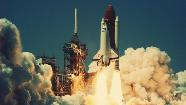
1. The Space Shuttle Challenger Disaster
The spaceflight of Space Shuttle carried a crew of 7 members, when it disintegrated over the Atlantic Ocean. The disintegration was caused due to the failure of one of Solid Rocket Boosters(SRB). The SRB failed during the lift-off.
The failure of SRB was caused due to O-Rings. O-ring is mechanical gasket that is used to create a seal at the interface. And here, that interface was between two fuel segments. O-Ring was designed to avoid the escaping of gases produced due to burning of solid fuel. But extreme cold weather on the morning of launch date, the O-Ring became stiff and it failed to seal the interface.
This malfunctioning caused a breach at the interface. The escaping gases impinged upon the adjacent SRB aft field joint hardware( hardware joining the SRB to the main structure) and the fuel tank. This led to the separation of the Right Hand SRB’s aft field joint attachment and the structural failure of external tank.
In the video below, the speaker mentions about the weather being chilly on that morning and icicles formed on the launch pad in the morning. One of SRB is clearly visible making its own way after the failure.
2. The Space Shuttle Columbia Disaster
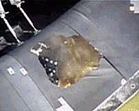
Unlike the above failure, this failure occurred during the re-entry. But again, the story traces back to the launch. During the launch, a piece of foam broke off from the external fuel tank and struck the left wing of the orbiter.
This is an image of orbiter’s left wing after being struck by the foam. The foam actually broke off from the bi-pod ramp that connects the orbiter and fuel tank.
The foam hit the wing at nearly a speed of 877 km/h causing damage to the heat shield below the orbiter. The piece of foam that broke off the external fuel tank was nearly the size of a suitcase and could have likely created a hole of 15–25 cms in diameter.
The black portion below the nose you see is the carbon heat shield of orbiter.
On Feb 1,2003 during the re-entry, at an altitude of nearly 70 km, temperature of wing edge reached 1650 °C and the hot gases penetrated the wing of orbiter. Immense heat energy caused a lot of dange. At an altitude of nearly 60 km, the sensors started to fail, the radio contact was lost, Columbia was gone out of control and the left wing of the orbiter broke. The crew cabin broke and the vehicle disintegrated.
You can clearly see the vehicle disintegrating. **The video is a big one, hang tight. 😉
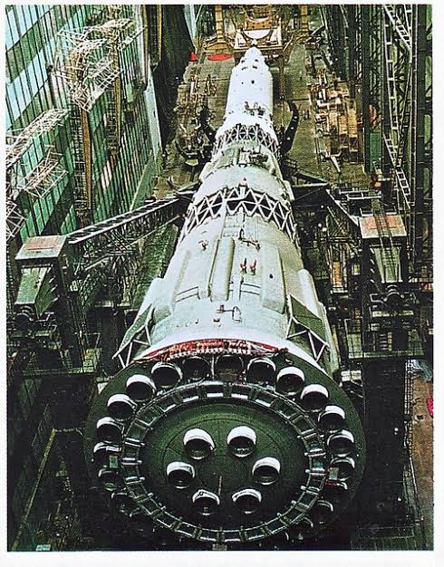
3. The N1 Rocket Failure
Not many people know about this programme. It was started in 1969 by the Russians. N1 rocket remains the largest rocket ever built till date. The rocket had its last launch in 1972. During this tenure, the were four launches, all of them failed. Yes you heard it right, ALL OF THEM FAILED.
Before discussing the failures, there is one thing that I never forget to mention about this rocket. Rockets rely on TVC(Thrust Vector Control) to change the direction of the thrust. The nozzle direction is changed to alter the direction of thrust.
This is TVC. But in case of N1 Rocket, there was something called Static Thrust Vectoring. There were 30 engines in stage 1, 8 engines in stage 2, 4 engines in stage 3 and 1 in stage 4.
There were 24 on the outer perimeter and the remaining 6 around the centre.
In order to change the direction of rocket, the thrust was changed in the engines accordingly. The engines didn’t move like TVC at all.
Now coming to the failed launches:
Launch 1:
The engines were monitored by KORD(Control of Rocket Engines). During the initial phase of flight, a transient voltage caused KORD to shut down the engine #12. Simultaneously, engine #24 was shut down to maintain stability of the rocket. At T+6 seconds, pogo oscillation( a type of combustion instability that causes damage to the engine) in the #2 engine tore several components off their mounts and started a propellant leak. At T+25 seconds, further vibrations ruptured a fuel line and caused RP-1 to spill into the aft section of the booster. When it came into contact with the leaking gas, a fire started. The fire then burned through wiring in the power supply, causing electrical arcing which was picked up by sensors and interpreted by the KORD as a pressurization problem in the turbopumps.
Launch 2:
Launch took place at 11:18 PM Moscow time. For a few moments, the rocket lifted into the night sky. As soon as it cleared the tower, there was a flash of light, and debris could be seen falling from the bottom of the first stage. All the engines instantly shut down except engine #18. This caused the N-1 to lean over at a 45-degree angle and drop back onto launch pad 110 East. Nearly 2300 tons of propellant on board triggered a massive blast and shock wave that shattered windows across the launch complex and sent debris flying as far as 6 miles (10 kilometers) from the center of the explosion. Just before liftoff, the LOX turbopump in the #8 engine exploded (the pump was recovered from the debris and found to have signs of fire and melting), the shock wave severing surrounding propellant lines and starting a fire from leaking fuel. The fire damaged various components in the thrust section leading to the engines gradually being shut down between T+10 and T+12 seconds. The KORD had shut off engines #7, #19, #20, and #21 after detecting abnormal pressure and pump speeds. Telemetry did not provide any explanation as to what shut off the other engines. This was one of the largest artificial non-nuclear explosions in human history.
Launch 3:
Soon after lift-off, due to unexpected eddy and counter-currents at the base of Block A (the first stage), the N-1 experienced an uncontrolled roll beyond the capability of the control system to compensate. The KORD computer sensed an abnormal situation and sent a shutdown command to the first stage, but as noted above, the guidance program had since been modified to prevent this from happening until 50 seconds into launch. The roll, which had initially been 6° per second, began rapidly accelerating. At T+39 seconds, the booster was rolling at nearly 40° per second, causing the inertial guidance system to go into gimbal lock and at T+48 seconds, the vehicle disintegrated from structural loads. The interstage truss between the second and third stages twisted apart and the latter separated from the stack and at T+50 seconds, the cutoff command to the first stage was unblocked and the engines immediately shut down. The upper stages impacted about 4 miles (7 kilometers) from the launch complex. Despite the engine shutoff, the first and second stages still had enough momentum to travel for some distance before falling to earth about 9 miles (15 kilometers) from the launch complex and blasting a 15-meter-deep (50-foot) crater in the steppe.
Launch 4:
The start and lift-off went well. At T+90 seconds, a programmed shutdown of the core propulsion system (the six center engines) was performed to reduce the structural stress on the booster. Because of excessive dynamic loads caused by a hydraulic shock wave when the six engines were shut down abruptly, lines for feeding fuel and oxidizer to the core propulsion system burst and a fire started in the boat-tail of the booster; in addition, the #4 engine exploded. The first stage broke up starting at T+107 seconds and all telemetry data ceased at T+110 seconds.
Besides the mechanical failures, the rockets might fail due to a minute discrepancy in program’s as in case of Ariane 5.
Ariane 5: After 37 seconds later, the rocket flipped 90 degrees in the wrong direction, and less than two seconds later, aerodynamic forces ripped the boosters apart from the main stage at a height of 4km. This caused the self-destruct mechanism to trigger, and the spacecraft was consumed in a gigantic fireball of liquid hydrogen.
The fault was quickly identified as a software bug in the rocket’s Inertial Reference System. The rocket used this system to determine whether it was pointing up or down, which is formally known as the horizontal bias, or informally as a BH value. This value was represented by a 64-bit floating variable, which was perfectly adequate.
However, problems began to occur when the software attempted to stuff this 64-bit variable, which can represent billions of potential values, into a 16-bit integer, which can only represent 65,535 potential values. For the first few seconds of flight, the rocket’s acceleration was low, so the conversion between these two values was successful. However, as the rocket’s velocity increased, the 64-bit variable exceeded 65k, and became too large to fit in a 16-bit variable. It was at this point that the processor encountered an operand error, and populated the BH variable with a diagnostic value.
That’s your answer to “why”. Rockets can fail anytime due even a small malfunction in one of those 2.5 billion dynamic parts or even a small programming error.
Probably you are going to witness the greatest technological feat of human civilization that remarks not just technological advancement but bespeaks one of the greatest establishment of humankind as a whole.
Moreover, on a special note, I would like you to consider the fact that it is the core human tendency to break his own records which every time seems to appear, the final last update. I would not claim for the future but comparing the past then certainly this masterstroke ranks first.
This whole story remarks some of the most distinguishing characteristics of human society. The story of the massive vehicle taking off from womb of mother earth with million-ton heavy rocket boosters and touching down back to earth with elegant astronauts inside. This signifies the display of greatest courage, dedication, commitment and above all international cooperation and brotherhood.
I assure you that none of my blogs has the capability to swing your mind like this can. If you want to experience a complete thrill then follow this blog after you go through the Higgs boson and nuclear fusion on earth.
So that was the warm-up part of the blog, let us uncover the bottom line of it.
FROM STAR-GAZING TO MARS MISSION
Humans earlier used to sleep under the open skies and this chance of glaring the ubiquitous, vast and boundless space, the world of stars and planet have ignited the humans to know and visit them someday.
From those days of dreaming, the history records the development of theories of movement of heavenly bodies by Galileo Galilei and Isaac Newton, the launching of first liquid-fuel propelled rocket by father of rocketry, Robert Goddard, then the first human in space from Russia and landing on the moon by America. Skimming through those pages we see a story of great ups and downs and we get to know how all those audacious and beautiful things were accomplished.
These achievements are not just for the sake of scientific fantasy, in fact, is aimed at providing the exceptional services of communication, aviation, and information technology as an immediate outcome. On the other hand, remarks the very first step of humankind to become interplanetary species so as to surpass the danger of extinction in the future due to earth turning hostile.
We have talked a lot about “in general” of the topic and let us turn to more technical aspects. Let us get to know more about some major technical details about the designing, launching and maneuvering, re-entering and landing of the space shuttles. Moreover, USA’s NASA has done a whole lot of work on the space shuttle. So we will talk specifically about those American space shuttles and also talk about major timeline events.
DESIGNING
This topic covers the aspects of the basic aerodynamics, fuel system, and the thermal protection system.
Requirements:
Light-weight: There is a whole lot of sensors, types of equipment, satellites that lead to the very heavy weight of the whole system. The gross weight reaches to 4.4 Million pounds of a typical space shuttle system at launch.
Structural integrity: The shuttle burns 1.99 Million kg of fuel in 8.5 minutes. Which pushes the shuttle from zero to 7850 m/s in orbit with an average acceleration of 29.4 m/s^2.
Reusability: The economy is the major coin side that determines the fate of any technology. Making the space shuttle partially reusable was also a major challenge.
Thermal protection: The temperature of the skin of space shuttle in its journey varies from -156 degrees in space to 1650 degree Celsius on re-entry. Advanced thermal systems are required to keep the temperature of highly explosive cryogenic propellant under required temperature and also prevent crew inside to get singed from this extreme heat or get frostbite in space.
Basic components:
So this is a typical space shuttle comprising of three basic units:
i) the orbiter, ii)the orange coloured external fuel tank(ET), iii) two solid- rocket boosters(SRBs).
Let us explore each element one by one and see what engineering challenges they presented and how it is fixed.
THE ORBITER:
This is the most significant part of the whole system. The reusable element of the space shuttle and that too up to 100 missions with minimal maintenance.
It is exposed to extreme temperature variations from -150 degrees Celcius in space when overlapped by earth’s shadow and 1600 degrees Celsius on re-entry. Moreover, it is supposed to produce massive accelerating forces by its own engines and thus requires high structural integrity to withstand those crushing forces on itself.
The most challenging part is an advanced reliable thermal protection system.
So, what’s the hack?
Like most of the time most complex problem is best addressed by the most simple solution, same is the case here.
So what is the best way to tackle heat?
The answer is INSULATION. Simply don’t allow the heat to enter the orbiter.
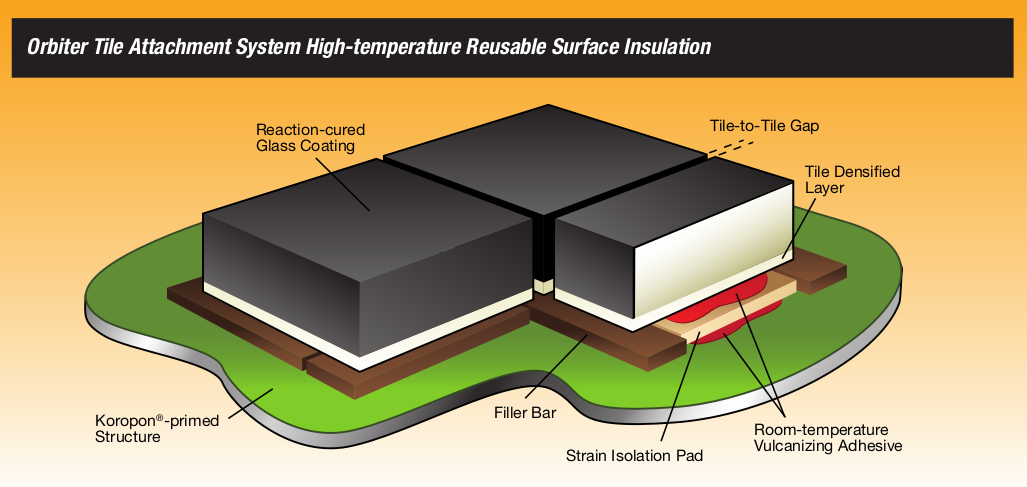
Engineers turned to simple silica sand to find an insulation material to operate at 1600 degrees. An ultralight highly porous block manufactured out of silica from sand which consists of 90% of air and rests10% special grade sand. These segments are called tiles. There are over 27,000 of these tiles on the shuttle of intricate shapes and design, all just as important as the next. Also, these tiles are not mechanically bolted on the body of shuttle instead glued with normal silicone adhesive on aluminium skull. In this way segmentation of tiles allowed for reusability by replacement of small damaged segments after every mission.
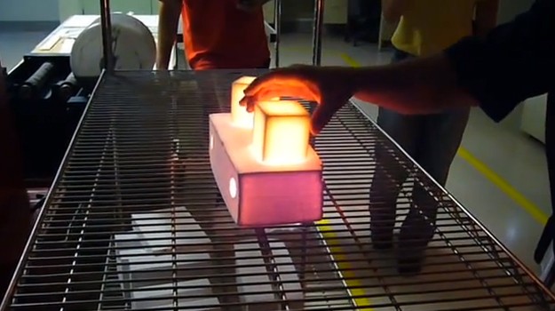
They are extremely good at heat dissipation. These tiles taken from a 2,300 oF oven can be immersed in cold water without damage. The surface dissipates heat so quickly that an uncoated tile can be held by its edges with an ungloved hand seconds after removal from the oven while its interior still glows red.
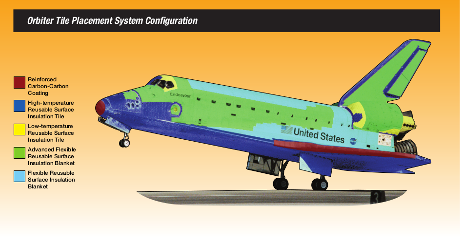
Also, the temperature is not distributed uniformly through the orbiter at re-entering. The base of craft sees much higher temperature compared to the top.Hence, different composition of tiles is used in different parts of the orbiter. The leading tips of wings experience the highest of all, touching the 3000 degrees Celcius mark. Thus they are specially made up of a composite material called reinforced carbon-carbon.
Probability of tile failure is not greater than 1/10 ^8.To accomplish this magnitude of system reliability and still minimize the weight didn’t come unpaid. It was only after the Columbia Shuttle disaster on 1 Feb 2003, investigations revealed the vulnerability of the ultralightweight tile to get punched by orbital debris. India lost its daughter Miss Kalpana Chawla in this disaster.
It was the aftermath of the unfortunate disaster that NASA pushed tougher to develop a highly secure and reliable heat shield, including the reinforced carbon-carbon composite for wing edge, which was the reason of melting of the shuttle on re-entry.
The STS-107 crew includes, from the left, Mission Specialist David Brown, Commander Rick Husband, Mission Specialists Laurel Clark, Kalpana Chawla and Michael Anderson, Pilot William McCool and Payload Specialist Ilan Ramon. (NASA photo)
This shot focuses on the bottom of an orbiter named DISCOVERY.
These short video summaries neatly the concept of the thermal protection system (TPS) using the tiles.
If we talk about electrical power availability for the instrumentations and other important operations then it is supplied by three hydrogen-oxygen fuel cells which is operated by the cryogenic storage tanks installed on the orbiter. They are capable of generating 21 kW of power at 28 volt DC which is then converted to 115 V, 400 Hz, three-phase AC power for orbiter and payloads.
Amazingly the byproduct of the fuel cell is water which is made available for use for crew onboard.
Now comes the backbone of the space shuttle at the launch, the most massive part of this giant, the external fuel tank (ET).
THE EXTERNAL FUEL TANK:
This 50 m high and 8 m in diameter ET provide the fuel to three main engines and structural integrity at launch, hence is known as the backbone of the space shuttle.
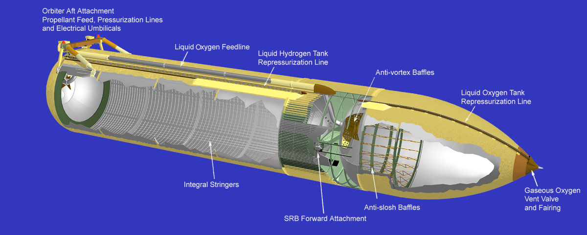
The ET carries cryogenic propellants i.e. liquid oxygen and liquid hydrogen for the combustion in three main engines on orbiter in two separate compartments divided by an unpressurised intertank that holds all the electrical components for proper operation.
An empty ET weighs around 35.5 Kilo Kg and it holds about 1.6 million pounds of propellants i.e a volume of about 2 million litres (enough to drive 1000 average cars round the year).
The ET supplies fuel to main engines on orbiter through two feed lines measuring 43 cm in diameter. The pressurised LO2 capable of flowing at a maximum rate of 66.6 thousand litres per min and LH2 at a max rate of 179 thousand litres per minute.
The ET is jettisoned after a burn time of around 510 seconds, after which it returns back to earth following a predetermined trajectory and lands in the remote ocean.
Physical structure:
The front chamber carries liquid oxygen at 250 kPa and at −182.8 °C in tank volume of 559.1 m3.
The intertank hoses all the operational instruments and also receive and distribute the thrusts from the SRBs.
The aft chamber carries liquid hydrogen at 300 kPa and −252.8 °C in 1,514.6 m3 tank volume.
Although hydrogen tank is 2.5 times larger than the oxygen tank but weighs only one-third as much when filled to capacity. The reason for the difference in weight is that liquid oxygen is 16 times heavier than liquid hydrogen.
Each fuel chamber also includes an internal slosh baffle and a vortex baffle to dampen fluid slosh due to vibrations.
Engineering challenge:
The thermal protection system is also critical for ET so as to maintain proper fuel temperature during the ascent of 8.5 minutes. Moreover, freezing ice at standby condition due to highly-chilled cryogenics on the skin of ET, which later form debris and impacts the orbiter glass shield or damages the tiles should be checked.
The ET is covered with a 1-inch (2.5 cm) thick layer of polyisocyanurate foam insulation, which also gives its distinguishing orange colour. The insulation keeps the fuels cold, protects the fuel from the heat that builds upon the ET skin in flight, and minimizes ice formation at standby.
The proper foam material selection only came after the loss of Columbia space shuttle in which insulating foam broke off the ET and damaged the left wing of the orbiter, which ultimately caused Columbia to break up upon re-entry.
This is a close view of the insulating foam on the ET.
THE SOLID ROCKET BOOSTERS:
These reusable boosters provide 70% thrust for liftoff of the space shuttle from the launch pad. They are 45 m high, 3.5 m in diameter and weigh up to 1.3 million pounds. The solid propellant that fuel consists of atomized aluminium (16 %) (as fuel), ammonium perchlorate (70 %) (acts as oxidiser), iron oxide powder (0.2 %) (acts as catalyst), polybutadiene acrylonitrile (12 percent) as curing agent and epoxy resin (2 percent).
They also bear the whole weight of shuttle on launch pads. With a burn time of 127 seconds, they are jettisoned and parachuted into the ocean and recovered by signalling devices and reused.
Not this element proved good to NASA and led to the disastrous crash of Challenger Shuttle,1986 due to a technical fault in the O-rings, killing all the crew on board.
The STS-51L crewmembers are: in the back row from left to right: Mission Specialist, Ellison S. Onizuka, Teacher in Space Participant Sharon Christa McAuliffe, Payload Specialist, Greg Jarvis and Mission Specialist, Judy Resnik. In the front row from left to right: Pilot Mike Smith, Commander, Dick Scobee and Mission Specialist, Ron McNair.
MISSION PROFILE:
LAUNCHING AND MANEUVERING
REENTRY AND LANDING
POST LANDING PROCESSES
BRIEF HISTORY
The credit of the science of space shuttle taking humans to space goes unravelled to NASA. The astronauts, scientist, and engineers who worked at NASA are entitled to standing ovations by the whole human society.
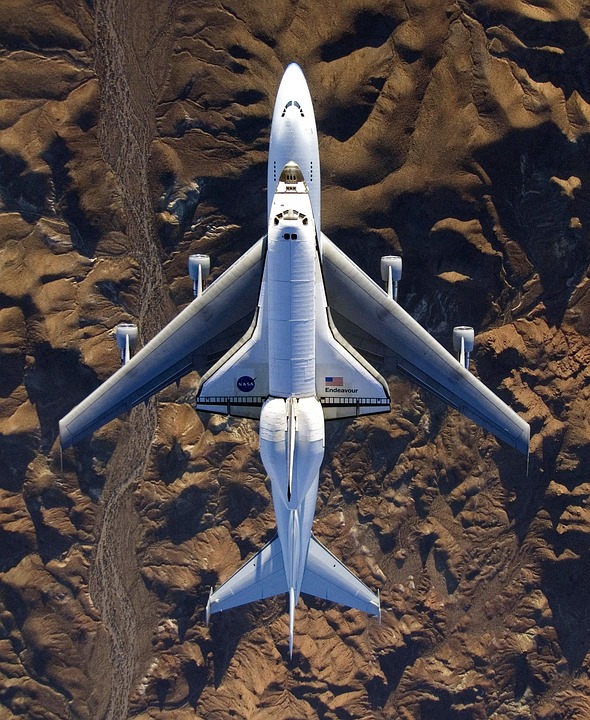
U.S started his visionary program called Space Transportation System (STS) and launched the first mission in the year 12 April 1981. The STS-1 named space shuttle Columbia successfully completed its orbital test flight. A fleet of 5 space shuttles named Challenger, Endeavor, Columbia, Discovery and Atlantis executed a total of 135 mission. Out of which two of them, Challenger (STS-51) and Columbia (STS- 107) failed that lead to loss of 14 crew members, rest other missions successfully scripted in pages of history. The space shuttle Atlantis (STS – 135) marked the last mission on 8 July 2011.
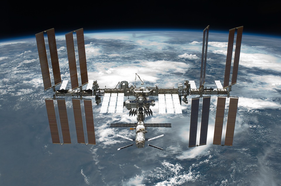
By the end of this mission, the world got the valuable gifts of ISS (International Space Station), Hubble Telescope, GPS technology, mobile communication, and many scientific experiments conducted in space. All of these technology forms the backbone of 21st-century human civilization and raises in us the hope of interplanetary successful human transportation someday!!!!
The biggest achievement of space missions: THE ISS
CONCLUSION
Humans might have used the science to attack enemy nation from space which could have possibly erased the existence of the whole planet, but fortunately, this marked the cradle for a technology which has now become the indispensable part of our life.
So, being a modern engineering marvel, it also led to the end of the cold war between the giants US and Soviet Union, which otherwise could have wiped the planet after leading to third world war.
FOR READABILITY ISSUES “THEMISSIONPROFILE” TOPIC WOULD BE COVERED IN NEXT BLOG.
In the end, a beautiful clip to experience the thrill of space shuttle launch…
Thanks for your kind attention and valuable time!!!
Stay tuned for the next blog, till then your doubts and thoughts are most welcomed.