An Insight into Indian Industrial R&D

Reading Time: 7 minutes

The following document records the working and insights of a R&D department of an Electrical Instrumentation Manufacturing company, born and bought-up in India in early 1980s, and eventually extending its roots over 70+ countries and sustainably competing in European, Middle-East, Russian, South-East Asian, American and Latin American, and of course Indian Markets. 

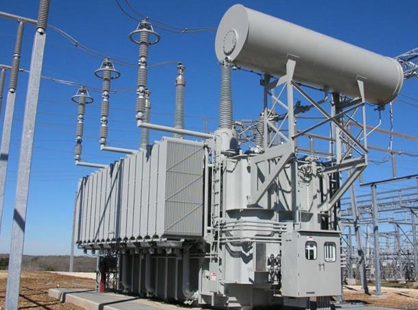
From advanced Multifunction Meters to legacy Analog Panel Meters, from handheld Multimeters to patented Clamp Meters, from Digital Panel Meters to Temperature Controller, from 10 kV Digital Insulation Testers to 30 kW Solar Inverters, from Current transformers to Genset Controllers, from Power Factor Controller to Power Quality Analyzers, from Batter Chargers to Transducers. From making best-selling products to white labeling for German, American, Polish and UK’s tech giants. From being major supplier of measuring instruments for BHEL, Railways, NTPC, and big and small manufacturing facilities in India to be able to send its devices in SpaceX rockets. This is not a description of a company located in a tech savvy Silicon Valley of most superior nation of world. This is description of just one of many such growing companies in far obscure industrial regions of our Indian sub-continent.   

Purpose of this accounting:

  1. To introduce and highlight the major working, thinking and organizing methods of a world that awaits the footsteps of the hopeful graduates out from a relatively cozy boundaries of their college campus.  
  2. To produce a testimony of fact that in exact same environment, with exact same people backed by exact same education system, with same so called incompetent Indian working class a company not just leads a product-based market but also beat it’s so called advanced European counter-parts and bring in collective consciousness the descriptions that seriously challenges the conventional assumption of ailing Indian Manufacturing Industry.
  3. To reinforce and bear witness to the fact that the truths and advices we all get to hear from people around us, are not mere variation of pressure in air but if followed with true spirit it literally creates magic and destined to get one to a point of breath taking, heart pounding and soul touching experiences.

Work on Solutions Not on Problems

The key spirit of professional execution is logical optimistic solution finding approach. The problems in front of all of us are all equally compelling and evident, absolutely no doubt in that, resources are limited, time is little, skills are moderate, support is not there, etc. But the point is the R&D mindset will never except them. If resources are not there let’s check-out the savings/loan, if time is not there let’s think about multiplexing, if skill is not there let’s talk to an expert and reach out for help, if support is not there let’s start reading ourselves. With optimism you ask, What exactly is the problem and what needs to be done to counter it, you present yourselves with options select one with maximum logical connections and go do it. If failed, with same optimism you ask that same question again. If you take decision with logical grounded thinking every time you almost hit the solution and in that is the drive for next try.

For example, in our setup, even on just one section of product (let’s say LCD) as many as 24 revisions are made until you uncover the design that has best readability with maximum features considering the space limitations of mechanical housing and even at that point the owner of design will not say no to 25th revision if that’s better than 24th. And here the catch is when someone starts, he can just say no, it is not possible to accommodate all these things on such a small screen, either readability or extra features can be provided, logically that’s correct until someone comes with an optimistic solution finding approach and say let’s first accommodate the unavoidable one, then let’s try some alignments, let’s try some tilts, let’s try some symbols, lets try some overlapping.

An Insight into Indian Industrial R&D

An striking example of human genius, the size of screen is less than a little finger of a 5-year old, but is capable to display great deal of data on it.

Doing Detailed and Exhaustive Documentation

It is well accepted and proven thing that if we work well with the documents at office, one is destined to have peaceful life at home, as one does not have to remember any dumb piece of information. You have a flawless access to a time machine kind of thing. A window to look your past works and track back any spurious design back to its origin in a very less time and less frustrating way. Without documentation at any point the situation which appears to perfectly under control can turn into a knife in windpipe type of jacked-up mess. So, maintaining organized folders, Read_Me files with time stamps and quick notes is indispensable.

Organization of Big and Small Things

Organization of assets and swift and flawless access to our resources always help us to do the mundane things in a highly efficient manner. Think about it you are working on your dream project and the time when you got a breakthrough idea in your work you spend next two hours searching the resistor in the plethora of mess you created and never finding it out and in a snip the time you got to try out that idea is gone. Life is fast for all of us, so being ever ready handy with our tools and hacks is always advantageous.

From the 15K Solder gun to a 1 Rupee pin that you may use to temporarily replace the fallen button on your shirt, everything shall be at its designated place. In such degree of organization of everything around us, one feels that readiness and calm to make it through all those massive problems that all of us have.

Organization of assets just not saves time, money and energy but always creates a welcoming environment to get into. And whichever phase of our lives we may be in a high-school student, a college grad or a professional, we can never isolate our work life from the usual personal life that has to go alongside. One may get ill, one may have unsettled debates with parents, one may have problems with food, water, home, discomfort with neighbors, heavy traffic and extra chilled office spaces, etc., all that non-sense that always plagues us, are anyways an inseparable part of life. The things that walk you through is that the highest degree of organization of small things, big assets and of course thoughts in the head.    

Choice is at Last Always Ours!

There comes a time when we all get stuck. Some gets resolved after few hours or debugging some stretches over a day, and some extend up to a working week. Rare are those problems that walk along your side for over a month’s duration. If someone is sufficiently in line with ongoing then most of time our divine intuition lets us get to the root of issues in one or two shots.

You found that EEPROM isn’t responding, you take out the datasheet verifies for the connections, check out the supplies found a cap dry, gave a magic touch with your gun and boom the EEPROM rocks.

You found that device is not measuring the current, you took out the circuit and assembly diagrams, verify the components, found all good. Took out the DSO and plug it across the shunts and find that the resistor is burnt. Replace it with new and, boom that’s fixed.

So, every time you take help of logical reasoning of what has to happen to make that happen and that pretty much shows the light. Eliminating one by one the most obvious reasons for the problems. This doesn’t take courage, but the fun starts to fade out as we run out of logical possibilities. It is from here the test of gut starts. When all logical traces have been checked, everything is just as expected to be, except the final output.

In those moments of defeat and dead-ends one gets subjected to an entirely new dimension of thinking which causes a serious humbling effect on professional’s character. When you look back at those time of intense desperations and using your most forceful impacts and still not hitting the thing, the only thing that comes from within is great calm and respect for the nature of reality for being whatever it is.

How would you handle a situation in which accidently a plugin slot gets locked by you in 5 Lakh high priority high-use equipment?

How would you handle the situation in which after months of workings you are just about to shoot for the hand-over of a product to the production and QA teams suddenly reports to you the most dreaded failure of your product, which is expected to drive a long process of iterative tuning?

How would you handle the situation in which you checked, double-checked, triple-checked and still an error made it into your product’s datasheet?

These types of situations lead to increase in speed of blood in veins, ringing in head, and absolute blow to our spirit and whatnot. But even in that chaos things really moves based on the choices we make. One can accept that truth as it is and chose to question what needs to be done and just take that one next step to address it or accept feeling desolated, beaten, and slapped by life like anything.

Choice is ours!

Try out these fundamental methods of organization, thinking and working, and get astounded by the power of it.

Conclusion

The sudden adoption of Western Education System inspired course structuring in Indian Education System has opened up a humongous range of possibilities for young new graduates. Few students find this ideal for their exploring journey, were as many struggle to chose what to pick from the such a large plate of options. The student needs to anticipate the common and advanced skills in their field of liking. Getting the intuition behind the theory, enabling oneself with mathematical tools and methods, getting comfortable with open source environments, getting hands fluent in hardware handling, ability to do documentation and working in an organized and structured manner, all these set of skills proves to be an asset for every team member during the product development.

The IP rights are conserved, names of companies and writer remains anonymous. 

James Webb Space Telescope

Reading Time: 12 minutes

INTRODUCTION

The curiosity about what was there 13.5 billion years ago and the search for the habitable planets might end. On 25th December 2021, NASA launched their massive 10 billion dollar endeavor, which will help humans look for what was there and what surprises the universe holds for us. The expensive James Webb Space telescope, simply called Webb, is named after James E. Webb, who served as the second administrator of NASA during the 60s and oversaw U.S. crewed missions throughout the Mercury and Gemini programs.
 

The JWST or Webb is a space telescope which is developed by NASA in collaboration with the European Space Agency and Canadian Space Agency. It will complement the Hubble space telescope and is optimized for the wavelengths in the infrared region. The JWST is 100 times more powerful than it. The diameter of the optical mirror of Webb is 6.5 meters making its collecting area 6.25 times more than Hubble. The Webb consists of 18 hexagonal adjustable mirrors made of gold-plated beryllium with just 48.2 grams of gold, about the same weight as a golf ball. Since the telescope is operating in the infrared region, the temperature around it needs to be very low to prevent the overwhelming of the sensors by the heat from the Sun, the Earth, and the heat emitted by its parts’. To overcome that the special material called Kapton with a coating of aluminum is used such that, one side facing the sun and earth would be around 85 degrees celsius while the other side would be 233 degrees Celsius below zero. Also, the problem of keeping the instrument’s temperature at an optimal level is solved by using liquid helium as the coolant. The telescope is going to have 50 major deployments and 178 release mechanisms for the smooth functioning of the satellite. The Webb was launched on Ariane 5 from Kourou in French Guiana and will take six months to become fully operational and is expected to work for 10 years.


The JWST project was being planned for 30 years and had to face many delays and cost overruns. The first planning was carried out in 1989 whose main mission was to “think about a major mission beyond Hubble”. There were many cost overruns and project delays throughout the making of the telescope. There were also many budget changes throughout the period. The original budget for making the telescope was going to be US$1.6 billion. Which was then estimated to be US$ 5 million by the time construction started in 2008. By 2010, the JWST project almost got shelved due to the huge budgets until November 2011 when Congress reversed the plan to discontinue JWST and set the cap of the funding at US$ 8 billion.


The telescope has been launched to study the early planets and galaxies formed after the Big Bang. The telescope would also help in finding out the formation of new planets and galaxies. The US Congress capped its funding to US$ 6 million.

ORBIT OF THE TELESCOPE

Being an infrared telescope, the position of the telescope in space is crucial for its desired operation. The telescope has to be as far as possible from the sun so that the sun’s infrared ways don’t interfere with the telescope’s instruments as well as not being too far away from the earth to stay in contact with NASA all the time. So NASA decided to put the telescope in Lagrange point 2 of the sun-earth system. So the question arises what is a Lagrange point and what is its importance. Let’s go back and learn how Lagrange and Euler discover these points in space. The Lagrange points are points of equilibrium for small-mass objects under the influence of two massive orbiting bodies. Mathematically, this involves the solution of the restricted three-body problem in which two bodies are very much more massive than the third. These points are named after the French Italian mathematician and astronomer Joseph-Louis Lagrange who discovered the Lagrange points L4 and L5 in 1772 but the first 3 points were discovered by Swiss Mathematician and Astronomer Leonhard Euler in 1772.


Joseph-Louis Lagrange was an Italian mathematician and astronomer. He made significant contributions to the fields of analysis, number theory, and both classical and celestial mechanics. In 1766, on the recommendation of Swiss Leonhard Euler and French d’Alembert, Lagrange succeeded Euler as the director of mathematics at the Prussian Academy of Sciences in Berlin, Prussia, where he stayed for over twenty years, producing volumes of work and winning several prizes of the French Academy of Sciences. Lagrange’s treatise on analytical mechanics written in Berlin and first published in 1788, offered the most comprehensive treatment of classical mechanics since Newton and formed a basis for the development of mathematical physics in the nineteenth century

Lagrange was one of the creators of the calculus of variations, deriving the Euler–Lagrange equations for extrema of functionals. He extended the method to include possible constraints, arriving at the method of Lagrange multipliers. Lagrange invented the method of solving differential equations known as variation of parameters, applied differential calculus to the theory of probabilities, and worked on solutions for algebraic equations. In calculus, Lagrange developed a novel approach to interpolation and Taylor theorem. He studied the three-body problem for the Earth, Sun, and Moon (1764) and the movement of Jupiter’s satellites (1766), and in 1772 found the special-case solutions to this problem that yield what are now known as Lagrangian points. Lagrange is best known for transforming Newtonian mechanics into a branch of analysis, Lagrangian mechanics, and presented the mechanical “principles” as simple results of the variational calculus.


Normally, the two massive bodies exert an unbalanced gravitational force at a point, altering the orbit of whatever is at that point. At the Lagrange points, the gravitational forces of the two large bodies and the centrifugal force balance each other. This can make Lagrange points an excellent location for satellites, as few orbit corrections are needed to maintain the desired orbit. L1, L2, and L3 are on the line through the centers of the two large bodies, while L4 and L5 each act as the third vertex of an equilateral triangle formed with the centers of the two large bodies. L4 and L5 are stable, which implies that objects can orbit around them in a rotating coordinate system tied to the two large bodies. Now the magic of L2 point is that it is behind the earth and the sun thus if we want to view the night sky without the earth’s intervention when can do it from this point and since it is in the Lagrange point it is orbiting in the same speed as the earth so it can be in continuous communication with the earth through the Deep Space Network using 3 large antennas on the ground located in Australia, Spain, and the USA and can uplink command sequence and downlink data up to twice per day and use minimal fuel to stay in the orbit thus increasing the lifespan of the mission.


The telescope is going to be 1.5 million km away from the earth and will circle about the L2 point in a halo orbit, which will be inclined with respect to the ecliptic, have a radius of approximately 800,000 km, and take about half a year to complete. Since L2 is just an equilibrium point with no gravitational pull, a halo orbit is not an orbit in the usual sense: the spacecraft is actually in orbit around the Sun, and the halo orbit can be thought of as controlled drifting to remain in the vicinity of the L2 point. It will take the telescope roughly 30 days to reach the start of its orbit in L2.


Unlike the Hubble telescope which can be easily serviced in case of damage, the James Webb Space Telescope cannot be repaired/serviced due to its significant distance(1.5 million km) from earth even more than the most distance traveled by the astronauts during the Apollo 13 mission in which they traveled to the far side of the moon which is approximately 400,000 km from earth. Therefore this is one of the riskiest missions in human history with 344 single points failure could lead to the end of the mission and years of research and hard work of thousands of scientists down the drain.

PARTS OF TELESCOPE

NIRCam:

INTRODUCTION:

NIRCam (Near-infrared camera) is an instrument that is part of the James Webb Space Telescope. The main tasks of this instrument include first as an imager from 0.6 to 5-micron wavelength, and second is as a wavefront sensor to keep 18 section mirrors functioning as one. It is an infrared camera with ten mercury-cadmium-telluride (HgCdTe) detector arrays, and each array has an array of 2048×2048 pixels. Also, NIRCam has coronagraphs which are normally used for collecting data on exoplanets near stars. NIRCam should be able to observe as faint as magnitude +29 with a 10000-second exposure (about 2.8 hours). It makes these observations in light from 0.6 (600 nm) to 5 microns (5000 nm) wavelength.


COMPONENTS:

The main components of NirCam are coronagraph, first fold mirror, collimator Pupil imaging lens, senses, dichroic beam splitter, Longwave focal plane, Shortwave filter wheel assembly, Shortwave camera lens group, Shortwave fold mirror, Shortwave focal plane


DESIGN:

NIRCam is designed by the University of Arizona, company Lockheed Martin, and Teledyne Technologies, in cooperation with the U.S. Space Agency, NASA. NIRCam has been designed to be efficient for surveying through the use of dichroic.


WORKING:

The Near Infrared Camera (NIRCam) is Webb’s primary imager that will cover the infrared wavelength range of 0.6 to 5 microns. NIRCam will detect light from the earliest stars and galaxies in the process of formation, the population of stars in nearby galaxies, as well as young stars in the Milky Way and Kuiper Belt objects.  NIRCam is equipped with coronagraphs, instruments that allow astronomers to take pictures of very faint objects around a central bright object, like stellar systems. NIRCam’s coronagraph works by blocking a brighter object’s light, making it possible to view the dimmer object nearby – just like shielding the sun from your eyes with an upraised hand can allow you to focus on the view in front of you. With the coronagraphs, astronomers hope to determine the characteristics of planets orbiting nearby stars.

James Webb Space Telescope

NIRSpec:

INTRODUCTION:

The NIRSpec (near-infrared spectrograph) is one of the four instruments which is flown with the James Webb space telescope. The main purpose of developing the NIRSpec is to get more information about the origins of the universe by observing the infrared light from the first stars and galaxies. This will also help in allowing us to look further back in time and will study the so-called Dark Ages during which the universe was opaque, about 150 to 800 million years after the Big Bang.


COMPONENTS:

Coupling optics, fore optics TMA, calibration mirror 1 and2, calibration assembly, filter wheel assembly, refocus mechanism assembly, micro shutter assembly, integral field unit, fold mirror, collimator TMA, grating wheel assembly, camera TMA, focal plane assembly, SIDECAR ASIC, optical assembly internal harness.


MICROSHUTTER:

Micro shutters are tiny windows with shutters that each measure 100 by 200 microns, or about the size of a bundle of only a few human hairs. The micro shutter device can select many objects in one viewing for simultaneous high-resolution observation which means much more scientific investigation can be done in less time. The micro shutter device is that it can select many objects in one viewing for simultaneous observation and it is programmable for any field of objects in the sky. The micro shutter is a key component in the NIRSpec instrument. Micro shutter is also known as arrays of tiny windows.


James Webb Space Telescope

FINE GUIDANCE SENSOR:

INTRODUCTION:

The fine guidance sensor (FGS) is a typical instrument board on a James Webb space telescope, this provides high precision pointing information as input to the telescope’s attitude control systems. FGS provides input for the observatory’s attitude control system (ACS). During on-orbit commissioning of the JWST, the FGS will also provide pointing error signals during activities to achieve alignment and phasing of the segments of the deployable primary mirror.


COMPONENTS:

THE FGS don’t have that much complex structure. so the following are the main components of FGS:- The large structure housing a collection of mirrors, lenses, servos, prisms, beam-splitters, photomultiplier tubes.


WORKING:

The FGS has mainly three functions in which this instrument was planted in our telescope:

1) TO obtain images for target acquisition. Full-frame images are used to identify star fields by correlating the observed brightness and position of sources with the properties of cataloged objects selected by the observation planning software

2) Acquire pre-selected guide stars. During acquisition, a guide star is first centered in an 8 × 8 pixel window.

3)  Provide the ACS with centroid measurements of the guide stars at a rate of 16 times per second.


DESIGN:


James Webb Space Telescope

MIRI:

The mid-infrared instrument is used in the detection process of the James Webb Space Telescope. Uses camera as well as a spectroscope, in detection helps in detection from 5 microns to 28 microns of radiation to observe such a large range of wavelength we use Detectors made up of Germanium doped with arsenic these detectors are termed as Focus plane modules and have a resolution about 1024 X 1024 pixels. The MIRI system needs to be cooler than other instruments to measure such a long wavelength range and provided with cryocoolers which consist of two elements i.e. pulse tube precooler and Joule Thompson loop heat exchanger to cool down the MIRI to 7 K while operating. Consists of two types of spectroscopes 


  • Medium Resolution Spectroscope- it is the main spectroscope that uses Dichroic and Gratings.

  • Low-resolution Spectroscope- it helps in slitless and long-slit spectroscopy with the help of double prisms to get the spectrum from range 5 to 12 micrometer. Uses Germanium and zinc sulfide prisms to get the dispersion of light.

James Webb Space Telescope

SUNSHIELD:

To observe faint heat signals the JWST must need to be extremely cold to detect those faint signals. Sunshield helps in protecting the telescope from heat and light from the sun as well as the heat of the observatory also helps in maintaining a thermally stable environment and helps in cooling to 50K. 

The sun shield is made up of a material named Kapton which is coated with aluminum and the two hottest plates facing the sun also have silicone doping to reflect heat and light from the sun. have high resistance and are stable in a wide range of temperatures. 

 The number of plates and shape of plates play an important role in the shielding process. Five layers are used to protect the telescope and the vacuum between each sheet acts as an insulating medium to heat. Each layer is incredibly thin and the layers are curved from the center. 


James Webb Space Telescope


Some quick facts regarding the JWST:

  • The Webb’s primary mirror is 6.5 meters wide. A mirror this large hasn’t been launched in space before.

  • It will help humans to understand the dark age before the time when the first galaxies were formed. 

  • As of now, the JWST is fully deployed in space and is in its cooldown to let its apparatus work at an optimum level. So let’s hold our breaths for the wonderful and exciting discoveries that are yet to come. 

The Social Dilemma

Reading Time: 7 minutes

“Nothing vast enters the life of mortals without a curse.”

In 2020, Netflix released a documentary drama movie named “The Social Dilemma” directed by Jeff Orlowski which explores the rise of social media and the damage it has caused to society, focusing on its exploitation and manipulation of its users for financial gain through surveillance capitalism and data mining. According to recent estimates, approximately 3.8 billion people are active on social media worldwide which means that today more people are connected than ever through various social media platforms. Look around yourselves, which are the most visited Apps on your smartphones, you get to know how deep social media has penetrated our life. When asked about the impact of social media, creators said that they had never imagined to which extent their product would go on impacting the lives of common people across the globe. Social media did a fantastic job in helping people in their difficult times, it helped in searching the donor for organ donation, helped the needy to get donations, helped students to get free study materials online very easily, helped beginners to start cooking and there are endless examples of how social media has helped humans. But something has changed over the years. The world is changing at an unprecedented rate like never imagined before and that not in a good direction. 


Earlier the social media platforms were used for sharing photos and videos and connecting to people. The Internet was simple at that time. Now social media platforms like Facebook, Snapchat, Twitter, Tiktok, Google, Pinterest, Reddit, Linkedin, etc. compete for our attention. 

Today’s big tech giant companies are making their product keeping three main goals in their mind:- 


1.) Engagement goal- They want to drive up usage and keep you scrolling on their platforms. They want you to scroll through their platforms as much as you can do. But the question is how do they do that, right? They do it by using the machine as persuasive social media actors. It is called persuasive technology. Let me explain by giving a reference to two studies that were conducted at Stanford University in the mid-1990s that showed how the similarity between computers and the people who use them makes a difference when it comes to persuasions. One study examined the similarities in personalities while another study examined similarities in affiliation. Research highlights of the study are below.


Research Highlights: The Personality Study:

  • Created dominant and submissive computer personalities 
  • Chose as participants people who were at extremes of dominant or submissive 
  • Mixed and matched computer personalities with user personalities 
  • Result: Participants preferred computers whose “personalities” matched their own. 

Research Highlights: The Affiliation Study:

  • Participants were given a problem to solve and assigned to work on the problem either with a computer they were told was a “teammate” or a computer that was given no label. 
  • For all participants, the interaction with the computer was identical; the only difference was whether or not the participant believed the computer was a teammate. 
  • The results compared to responses of other participants: people who worked with a computer labeled as their teammate reported that the computer was more similar to them, that it was smarter, and that it offered better information. These participants also were more likely to choose the problem solutions recommended by the computers.

2.) Growth goal- They want you to connect with your relatives, your friends, even strangers and make them your friends, explore various attractive locations, crave tasty food, invite more people on the platform for engagement, etc. for one and only one reason, You visit their platforms more and more. Let me give you some examples from your daily social media experience. There are two forms of interactions that take place on Facebook: active interaction (liking, sharing, commenting, reacting) and passive interaction (clicking, watching, viewing/hovering).


  • Active interaction: Whenever someone likes your post or vice-a-versa, it gives a sense of joy that they like us or we like them. It creates a loop for you and them to visit each other’s profile more often and chat which means you will chat with them on social media platforms and you visit more. You share memes with them, react to their stories, you react to their reactions and ultimately you end up spending more time on their platform. It also creates a rat race for more no. of likes which can affect mental health. The more you crave for likes, the more you are expected to spend time on social media figuring out how you can increase your likes and get recognition amongst your peers. Below is the excerpt from a study on “The social significance of the Facebook Like button” by Veikko Eranti and Markku Lonkila.
The Social Dilemma

The figure suggests, first, that the relationship with the original poster of an object may have an impact on likes: We are more prone to like a post by a close Facebook friend than one by an acquaintance whom we have accepted as our friend somewhat reluctantly. Second, the quality, number, and network structure of previous likers are likely to affect one’s likes. This is probably even truer in the case of a sensitive or contradictory topic (e.g., a post on a political issue). Thus, if F1, F2, and F3 are close friends, F3 is more prone to like a post of controversial nature if F1 and F2 have both already liked it. Third, the imagined audience constructed subjectively by the user of the pool of all Facebook friends (some subset of F1–F4) is likely to influence liking behavior. 

  • Passive interaction: Now remember when you were not talking with anybody, not reacting to any stories, not commenting on any post but still active on social media, what were you doing? You were seeing videos and simply scrolling through various posts, memes, videos, reels hoping for the one post that you may find interesting and can like or comment on it, isn’t it? How long it took you to find the post you wanted to see. Probably not too much, your social media platform did not take a long time to guess what you want to see, but the question is how? Adam Mosseri, head of Instagram might answer your question, “Today we use signals like how many people react to, comment on, or share posts to determine how high they appear in News Feed. With this update, we will also prioritize posts that spark conversations and meaningful interactions between people. To do this, we will predict which posts you might want to interact with your friends about and show these posts higher in the feed. These are posts that inspire back-and-forth discussion in the comments and posts that you might want to share and react to – whether that’s a post from a friend seeking advice, a friend asking for recommendations for a trip, or a news article or video prompting lots of discussions.”
The Social Dilemma

3.) Advertising goal- When two people are connecting on the social media platform for free, it’s obvious someone is paying for it. A third party is paying for manipulation for those two, the other two, and every other person who is communicating through social media. We are in the era of surveillance capitalism where big tech giants are collecting a massive amount of data and collecting them at one place to show personalized ads to their customers and earn maximum money from advertising. It’s the gradual, slight, imperceptible change in your behavior and perception that is the product.


“If you’re not paying for the product, then you are the product.”


In one of the experiments conducted by Facebook on “Experimental evidence of massive-scale emotional contagion through social networks,” they found, “people who had positive content reduced in their News Feed, a larger percentage of words in people’s status updates were negative and a smaller percentage were positive. When negativity was reduced, the opposite pattern occurred. These results suggest that the emotions expressed by friends, via online social networks, influence our moods.” that suggests that Facebook can now affect or say change one’s real-life behavior, political viewpoint, and many more things. Effects of it have been felt across the globe in the form of fake news, disinformation, rumors, etc. Terrorist organizations used the very same formula and brainwashed hundreds of thousands to fight for them and kill innocent people. Now very same techniques are used by right-wing hate groups across the globe like white supremacists groups. We have seen examples of mob lynching in India due to rumors spread in the area. It is not just about fake news but it has more dangerous fake news of consequences. According to a recent study, fake news is five times more likely to speak than real news. We are transforming from the information age to the disinformation age. Democracy is under assault, tools are starting to erode the fabric of how society works. If something is a tool, it genuinely is just sitting there, waiting patiently. If something is not a tool, it’s demanding things from you. It’s seducing you. It’s manipulating you. It wants things from you. And today’s big tech giants have moved away from having a tools-based technology environment to an addiction and manipulation based technology environment. 


“Only two industries call their customers ‘users’, illegal drugs and software”


Big Tech giants namely Facebook, Amazon, Apple, Alphabet, Netflix, and Microsoft have grown tremendously over the past years. They have established monopolies in their respective industries where other smaller companies are either wiped out or struggling very hard to survive. The reason behind this is the cutting-edge technology developed by these companies which other companies can’t even compete on with them along with the unbelievable amount of data that they possess which makes their innovation more effective.

The Social Dilemma

Steps can be taken to make people aware of social media and its dangers. Chapters or subjects can be introduced at school levels to make children aware of the difference between social media and social life. Monopolies of the companies can be destroyed by the governments using anti-trust laws which would allow more competitors to enter the industries and create a safe and user-friendly environment on social media platforms. And lastly, strict laws should be made on data privacy and data protection.


“Any sufficiently advanced technology is indistinguishable from magic”


Making of 21st Century Solar Cell

Reading Time: 12 minutes

The manufacturing sector has been on the ventilator for a long time……

Despite a demand of 1.36 B we import quite a large portion of the products employing moderate to high-level technology, from electronic toys to smartphones to high power Induction motors of Indian Railways Engines. We don’t have any airliner manufacturing except HAL, we don’t have chip manufacturing even though we are land of powerful the Shakti microprocessors. How much sadness this fact bring home to us!

Consider Solar Cell & Module Manufacturing industry.

We have a small number of solar modules manufactures who import solar cells largely from China & Taiwan paste them on a tough polymer sheet, use some power electronics and meet the large demand of India solar needs.

We have even much small solar cell capability, who import wafers, own some mega turn-key solar line manufacturing unit mostly set up by European Companies. You see, we have to be very precise in claiming what is ours and what is not.

We import 80% solar cells and solar modules and a domestic manufacturing capacity of only 3 GW for solar cells. -Source: livemint.com 

In this blog let us at least critically understand what goes in the making of 21st century solar cell. And try to figure is that so hard, that we really need to import end-tailored billion euros turnkey lines to get the solar industry flying.

For good assimilation of the content, one needs to be familiar with a solar cell. One might answer the following question to get a temporary check-pass.

  1. How does charge generation, charge separation and charge collection phenomenon occur in a solar cell?
  2. What is meant by the short circuit current and open-circuit voltage of cell?
  3. Difference between the solar cell and solar module.
  4. On what factors does the form factor depend?

Notice the nature of the question, they are descriptive and have straight forward answers.

We don’t have here full degree of freedom to ask any wild question. For example, one cannot ask what would be voltage measured by non-ideal voltmeter across the photocell under no illumination, would current flow through external resistance in a not illuminated solar cell or a regular diode.

The reason is, from the engineering point of view we always study an abstract model of a solar cell or p-n junction. Physicists have very smartly built a layer over all the intricate things going inside the cell, we don’t care much about the exact phenomenon inside of the device, yet with the help of modified equations, we can deduce engineering relevant parameters like FF, Rsh, Rs, Isc, Voc, etc and can do clever things like MPPT, etc.

Similarly, using our conventional theory, one cannot explain the presence of intrinsic carrier at room temperature.

A pure silicon crystal has a bandgap of 1.12 eV, electrons on the other hand according to classical theory have thermal energy of kT (i.e. 0.026 eV or 26 meV). So intuitive physics would lead us to conclude that at room temperature there should be no electron in the conduction band. Still, at 25 degrees 10^10 electrons per cubic cm are available in the conduction band in a pure silicon crystal, called as intrinsic carrier density.

Think for a second how would you explain this paradox?

All these questions, wild or sober, can surely are answered satisfactorily (multiplying and integrating maxwell Boltzmann density of states and Fermi-Dirac probability distribution) but the point I want to highlight is that they really unfold the need of another kind of theory to explain, and let us reveal to you that is what the world knows as the quantum theory of matter.

Notice the power of our wild questioning, one correct question has simply enabled us to knock the door of mighty quantum physics. What a pleasure to discover for ourself the need for new theory, the theory which the world has been developing for the past 130 years.

On the other hand, if we think we are done with the p-n junction, simply-just by being able to describe the formation of depletion region and calculating the build-in voltage by a sweet formula without a taste of weirdness of quantum physics, then we should really reconsider our beliefs.

The flow

Ingot Growth

Wafer Slicing

Saw Damage Etch

Texturing

Emitter Diffusion

Anti-Reflection Coating

Front Contact

Back Contact

Firing

This blog won’t be really spitting out crude information throughout as it seems from the flow, rather it aims to induce self-questions in readers and thus provokes the reader to discover for themselves the tight constraint the solar cell manufacturing posses at every stage.

Now the first input is the silicon wafers. It itself takes a whole manufacturing industry, it has it’s own difficultly why India doesn’t have that, so we will not dive deep rather just walk through it until solar domain actually begins, you can even directly jump to Saw damage etch.

INGOT GROWTH

Silicon crystal falls broadly in two categories the monocrystalline silicon and polycrystalline silicon. Monocrystalline crystals contain continuous single crystal orientation.

Making of 21st Century Solar Cell

Polycrystalline crystal, however, has much less regularity, and have many grain boundaries. The solar industry is always on toes to minimize the cost per unit energy produced as its competitor is the outlet in our homes, so it can’t afford at any stage a high price manufacturing technology.

Making of 21st Century Solar Cell

Polycrystalline silicon is formed using the Siemens process, a faster and cheaper growth method as compared to Czocharalski, and float zone process for crystalline silicon.


Wafer Slicing

The next obvious step is the sawing out the wafers, evident from the ingot structure that the monocrystalline will be circular and polycrystalline will be square type. Slurry based sawing and diamond-based sawing are two popular techs, out of which diamond-based become much popular because it is fast and produce more yield as silicon dust produced is less.

No matter what techniques is used the roughness on the surface is way more than acceptable for the solar use or any (IC industry).

      Making of 21st Century Solar Cell

 Pseudosquare shape to optimize the material requirement  Making of 21st Century Solar Cell

Saw damage Etch

Enough of the peripheral walks, now we are entering the woods, from here we are entering the solar manufacturing.

To smooth out the scratches and remove the surface contaminants caused by sawing, the p-doped wafers are treated with a strong hot alkaline bath, like NaOH or KOH. We can also leverage the non-uniform surface to increase the probability for light to enter the silicon but it’s avoided as any deep crack has a chance to develop into a larger hairline fracture as Silicon is brittle at room temperature and hence breaking cell in some time.

The alkaline solution dissolves the 5-10 um thick layer from both ends, resulting in very fine surfaces and a p-type wafer of width in the range of 170 um. Precise control of temperature, concentration and time is required in the bath for desired outcomes.

Texturing

If the surface is perfectly smooth the light won’t get any chance to re-strike the surface again. The greater the number of times the light is reflected by the surface the more chances it has to enter the bulk of the silicon. However, for adequately rough surface the light reflected from the edges have more chances to enter the silicon.

Making of 21st Century Solar Cell

Image courtesy: pv-manufacturing.org

The process of saw damage etching and texturing only differ in concentration and temperature of alkaline. A much lower concentration alkaline is observed to yield pyramid-like structure over the silicon surface, which aids the cell to greatly reduce the reflectivity of the surface.

Making of 21st Century Solar CellImage courtesy: pv-manufacturing.org

A great amount of attention is given to tiny-tricky light management techniques. Using the principles of optics, the solar cell is optimized to somehow get the maximum photons inside (or increase the path length inside the silicon). These include Texturing, anti-reflection, back internal reflection, etc., in fact you would be surprised to know that attempts have been made by some companies to even texture the surface of fingers and busbars to divert the light falling on them towards the silicon, and like that.


Emitter Diffusion

The presence of the electric field is inevitable for charge separation as photons knock out the electron from Si atoms. Thus, next in line is the formation of the n-type region to develop a depletion region (p-n junction) inside the cell which assists in change separation.

The process is quite straight forward. We have a heated POCl3 gas inside a chamber and correct temperature and vapour density are maintained to allow the phosphorous atoms to diffuse into the silicon base.

The trick is how will one decide the doping density of the emitter layer and the thickness of it.

High doping density is desirable to have a good contact (less metal contact resistance) and low lateral series resistance as charges moves along the emitter, however higher doping density causes to decrease the bandgap of Silicon (as at extreme doping the crystals begins to become highly irregular, thus shrinking the band-gap) hence the blue light (high-frequency radiation) is not absorbed well, also recombination ( a type called Auger Recombination) increases in emitter leading to dragging down of the open-circuit voltage of the cell and hence the performance.

Now think about the thickness of emitter, ideally, the emitter should be narrow so that the time it remains inside the gas chamber is less and the process is faster and cheaper.

But if it is narrow there is a great chance that the metal will leach through it into the p-type directly shunting them, leading to extremely poor-quality cells.

Notice that every piece of solar cell development is a tight problem of optimization.

We require two contrasting qualities of the emitter, narrow and lightly doped for good light response and low recombination, and deep and heavily doped for good contact and low series resistance.

Selective Emitter is quite a smart way to accommodate both of them.

A shallow lightly doped emitter is formed first then by proper masking deep heavily doped contact regions are obtained.

Making of 21st Century Solar Cell

Anti-reflection Coating

This is one more way to increase the probability of light to get absorbed in the solar cell. Using a Silicon Nitride coating the light is reflected back into the cell.

The process generally used is called PVCED (Plasma Enhanced Chemical Vapor Deposition).

Making of 21st Century Solar CellImage courtesy: pv-manufacturing.org

Silane (SiH4) and Ammonia (NH3) are filled in a chamber and excited by high-frequency waves. Obeying the rules of chemistry and fine-tuning the process an extremely thin 70-nm layer of Silicon Nitride is formed above the emitter junction.

The added benefit is that the hydrogen released in the process bonds with dangling Si atoms which otherwise would have led to increased recombination, anyways this process of filling the holes is called passivation.

Making of 21st Century Solar Cell

The way in which this anti-reflecting coating works is truly an elegant piece of physics.

They work on principles of interference. We know that rays of monochromatic light can interfere depending on the distance (optical) travelled, as it causes a change in phase. The famous Michelson experiment produced constructive interference if path difference was λ, 2λ, 3λ, whereas produced destructive interference for λ/2, 3 λ/2, 5λ/2, etc.

Making of 21st Century Solar Cell

Magnified ARC layer

On similar lines, these 70 nm manages to produce a destructive interference of waves, thus suppressing the reflection from the surface and constraining the entire intensity to get transmitted.

For normal incidence the light travels twice the thickness of ARC, so for destructive interference, the optical path length difference between the two waves must be λ/2. Due to decreased speed of light inside higher refractive index material, the optical path length will increase by a factor of n.

Making of 21st Century Solar Cell

Where n is the refractive index of ARC.

Now, solar radiation is not monochromatic, hence we can never obtain destructive interference for all the wavelengths for one thickness of ARC. Thus, the thickness is optimized for wavelength at which peak of solar radiation occurs, i.e. 2.3 eV (550 nm). Given Silicon Nitride has refractive index of 2, plugging in the numbers we get:

Making of 21st Century Solar Cell

It is here from where we get the golden number of 70 nm, which is so popular in solar cell industry.

Front Contact printing

This is also one of the typical optimization problems in solar cell design.

For good ohmic contact (low contact resistance) the fingers must be wide, but for maximizing the amount of light entering inside the cell the fingers must be as narrow as possible.

Even finger spacing is a critical design parameter. Small finger spacing is desirable to keep the series resistance low, but it will lead in a larger portion of cell area to get shadowed by the front contact, again an engineering decision has to be made to optimize the net performance.

In fact, optimization constraint occurs in one more dimension here, the height of the fingers. One would like to have increased height to increase the cross-section for the current but again it would be limited as when the sun falls slantly the large shadow of these fingers would be casted if the height is large.

Same problem for the busbars too.

However, once the design is optimized the printing as easy as t-shirt printing. Making a mask and applying the paste and then drying.

Generally, a silver-based paste is used for the purpose.

Making of 21st Century Solar Cell

Back Contact Printing

Back Contact seems simple at first sight but like all the solar cell stuff it too poses optimization problems of its own. The Solar cell is supposed to operate in quite large temperature ranges.

Silicon has a lower thermal expansion coefficient than that of the metallic aluminium. If appropriate care of thickness of aluminium back is not taken then the difference in thermal coefficient might lead to intolerable bending of the cell, leading to even separation of contacts in the extreme case.

A layer of aluminium is developed on the back surface, the thickness of which typically lies in the range of 30 um.

However, this Al layer has an added benefit of what is called the back-surface field (BSF). Some of the Al diffuse into the p-type base and thus making it p++ type. The direction of the field developed to repel the minority carrier electron away from the back surface, and this also reduces recombination at back.

Making of 21st Century Solar Cell

Firing

Technically called post-deposition high-temperature annealing.

Notice that the front metal doesn’t make electrical contact with the emitter. So, the cells are lastly sent in a furnace of accurately controlled temperature. The heated silver etches through the tough 70 nm ARC and makes just suitable contact with the emitter.

This process has to be very finely tuned if the temperature is not high or cell is kept in the furnace for small-time the contacts will not be firm and hence result in high series resistance. If the temperature is high or the time is more than the molten silver will breach through the emitter to base, thereby directly shunting the device and giving rise to extremely small shunt resistance and hence again a poor performance device.

Making of 21st Century Solar Cell


Conclusion

The General Conclusion:

One can conclude for ourself that the manufacturing of solar cell is not so advanced as engineering quantum systems like manipulating Q-bits or fusion of atoms or replicating human brain, it is an arena of extreme fine-tuning and very precise control of temperature, concentration, motion.

The Technical Conclusion:

The solar cell is the best example of a most well-optimized system, in the real commercial scenario, it takes into account 30+ parameters.

It is also a standing example that little things in life matters and sometimes even more. Just like a team is only fast as slowest guy in the team similarly any engineering system is only efficient as least efficient component in the system, so nothing has to considered trivial or irrelevant or less worthy of attention, and it applies equally to life and non-living systems.

Some cool websites to learn and understand the solar cell in greater deaths:

1. pveducation.org

2. pv-manufacturing.org

Keep Reading, keep learning,

Team CEV!

Featured Image courtesy pixabay.com.

3 Horizons of Innovation

Reading Time: 6 minutes

- by Aman Pandey

Being in a technical club, we often discuss about innovation 💡 . Anyways, it is not just about being in a tech club 🔧 it is all about being a visionary, you frequently ponder into the thoughts of How an Idea come into existence

Ever thought about actually making a solution and creating its “actual” value 💸. (don’t care, it’s just an emoji). Value is not always about money, it about how much and how great effect it is making on the lives of this magnificient earth 🌏 . Money is just a side effect of creating value.

" A very simple definition of innovation 💡 can be thought of as A match between the SOLUTION 🔑 & the NEED 🔒 that creates some form of VALUE. "

It is all about the game of a GOOD Product strategy, that turns the solution into a value.

Whenever a new solution is launched for the society, it curbs across a different set of people 👥 👤 . Infact there’s a chart which will explain the things better than anything else.

https://miro.medium.com/max/1540/1*2kIL4HV7-y2MbzfMRmHQAQ.jpeg

You see the first portion of the curve? The Innovators? These are more of a tech enthusiasts 📟 who are crazy about any new technology, and just want to innovate. Then the Early Adopters ☎️, who actually see some value in the solution. These are the Visionaries 📣 . They are willing to see through business and value of a solution. Then comes the Early Majority, known as the Pragmatist 😷 , they are the first adopters of a technology in the market. They always seek out to improve their companies’ works by obtaining the new technology. Rest are the Late Majority, popularly known as skeptics, they usually look out for recommendations and then the Laggards, idk what they are called.

So there are certain strategies involved in the phases of transiting an innovation to a startup and to a company. This processs is known as Customer Development.

Oh wait ⚠️, looks like we forgot something.

You see a little gap 🌉 between the early adopters and the early majority, The Chasm. This is prolly the hardest and most important bridge that a solution needs to cover in order to create its value 💸 .

There are many startups which might make to that side of chasm, and the startups which might not make. In the most common terms, the first set of customers/buyers of your tech, who agrees to give a try on your innovation.

But, let us keep it for some other time.


Now the stuff, might depend upon certain criteria.

  1. There already exists some market and you want to capture that market.
  2. There are several markets, and you want to Re-Segment them according to your innovation.
  3. You don’t have any market, i.e. you create your own for your product.

But this is the talk of some other time. Let’s pretend we are not going deep into this. We know that, we have a market, which already have customers, a market which exists but isn’t used, and the market, which is still out of existence. You understand the difficulty in all the cases right. 📈


Baghai, Coley, and White came up with something in 2000, called as the Three Horizons of Innovation., more formally known as McKinsey’s Three Horizon of Innovation.

Let us now understand this, with a little example of Sleep medicine industry. 💊

According to a study, in America, around 5~10% population is affected by insomnia, and 2-4% by Sleep Apnea. So, there is already a good market.

Now, the disruption in sleep medicine industry led to a several researches 🔎.

One research was super disruptive, the innovation of Transcranial System.

After a lot of researches on its subjects, collecting data through fitbands, and devices like Beddit which were kept under the mattress of the subject, the researchers collected a lot of data about sleeping patterns. The researchers 🔎, came with the solution of Transcranial systems, which is a device, in which changing magnetic fields stimulates the brain signals and lets you sleep.

https://upload.wikimedia.org/wikipedia/commons/thumb/3/38/Neuro-ms.png/285px-Neuro-ms.png
Source: Wikipedia

And most of all, this is an non invasive device, i.e. it need not to be planted inside your brain. How do you think the researchers were able to do this?

Well this is all because of Artificial Intelligence.

  • The wrists bands ⌚️ used to monitor sleep activities. The fitbit bands accumulated around 7 billion nights of sleep😪.
  • The beddit devices, were kept under the mattresses, that records your pulses(could not record your oxygen levels though).
  • Apple🍎 watches, are so sharp in their tracking systems, that sometimes they are used as medical diagnosis devices.

So, what transcranial systems do, they track the abnormal pattern in the sleep signals, and send electrical signals, to let the person sleep comfortably.


Now there’s a bigger picture to understand here. If such a solution exists, then why ❓ is it not being used.

To understand this, let us now see the 3 horizon of Innovations:

https://innovationpapers.files.wordpress.com/2018/03/innovation-horizons.png?w=458&h=424

The horizontal axis, is about how new the innovation is, and the vertical axis is about the novelty of the market, that if the users already exists.

-> The Trancranial System lies, somewhere in the bottom right, where we know the existing market, which in this case are the APNEA patients, but the tech is still new to be used.

This makes it a bit difficult to convert this innovation to a company. 🎬

This still needs a lot of research and finally the makers have to tamper the already existing market, and bring in their device.

Let us take one more example. Support your plan to make a device, that tracks the breathing patterns or pulse rate, and you get data on your mobile phone. Now this data, after going through a series of AI models, lets the Doctor diagnose the severity of the disease and correctly cure you. ⭕️

In this case, you know the solution, and exactly what might solve your problem. Plus hand, you know the target customers. So is possible that this product can be shipped like in the next month.

This App lies somewhere in the lower left.

Now, let me clarify something for you.

  • Horizon 1 is considered to be of Not Much risk ⚪️, and these just need the improvements and cost reductions from the item the customer used before this (because you are targeting already existing customers)
  • Horizon 2 is the More Risk zone🔵 , and thus should be approached with care
  • Horizon 3 is the Highest risk zone 🔴, and you never know, whether the innovation will be able to even make it to that side or not. And might even take next 5 years to come into proper existence.

So, looking at the picture, from the farther point, we spot a sense of the patience and efforts required to give an innovation, a value.

Just like, Apple beat blackberry by making a device which served more as a personal device, unlike Blackberry which focused only on business users. So, in a short span of time, just in 2 years after launching iPhone in 2007, it took over Blackberry as the leading Mobile phone seller in the world.

You have to be a visionary to understand it.

Thank You.

Courtesy: CHRISTIAN TERWIESCH

The Harmonic Analyzer: Catching the Spurious

Reading Time: 10 minutes

“Do you have the courage to make every single possible mistake, before you get it all-right?”

-Albert Einstein

**Featured image courtesy: Internet

THE PROJECT IN SHORT: What this is about?

The importance of analyzing harmonics has been enough stressed upon in the previous blog, Pollution in Power Systems. 

So, we set out to design a system for real-time monitoring of voltage and current waveforms associated with a typical non-linear load. Our aim was “to obtain the shape of waveforms plus apply some mathematical rigour to get the harmonic spectrum of the waveforms”.   

THE IDEA: How it works?

Clearly, real-time capabilities of any system are analogous to deployment of intelligent microcontrollers to perform the tasks and since this system also demanded some effective visualization setup, so we linked the microcontroller with the desktop (interfacing aided by MATLAB). Together with MATLAB, we established a GUI platform to interact with user to get the required results:

  1. The shape of waveforms and defined parameters readings,
  2. Harmonic spectrum in the frequency domain.  

The voltage and current signal are first appropriately sampled by different resistor configurations, these samples are then conditioned by analog industry’s workhorses, the op-amps, and are fed into the ADC of microcontroller (Arduino UNO) for digital discretization. These digital values are accessed by MatLab to apply mathematical techniques according to commands entered by user at the GUI to finally produce required outcome on screen of PC.

The Harmonic Analyzer: Catching the Spurious

ARDUINO and MATLAB INTERFACING: Boosting the Computation

Arduino UNO is 32K flash memory and 2K SRAM microcontroller which sets limit to the functionality of a larger system to some extent. Interfacing the microcontroller with a PC not only allows increased computational capability but more importantly it serves with an effective visual tool of screen to display the waveforms of the quantities graphically, import data and save for future reference and so on.

TWO WAYS TO WORK: Simulink and the .m

The interfacing can be done via two modes, one is directly building simulation models in Simulink by using blocks from the Arduino library and second is to write scripts (code in .m file) in MatLab by including a specific set of libraries for given Arduino devices (UNO, NANO, etc.).

Only the global variable “arduino” needs to be declared in the program and rest codes are as usual and normal. We have used the second method as it was more suitable for the type of mathematical operation we wanted to perform.

NOTE:

  1. The first method could also be utilised by executing the required mathematical operation using available blocks in the library.
  2. Both of these methods of interfacing require addition of two different libraries.

THE GUI: User friendly

Using Arduino interfaced with PC also gives another advantage of user-interactive analyzer. Sometimes the visual graphics of waveform distortion is important and sometimes the information in frequency domain is of utmost concern. Using a GUI platform provided by MatLab, to give the option to user to select his choice adds greatly to the flexibility of analyzer.  

The GUI platform appears like this upon running the program.

The Harmonic Analyzer: Catching the Spurious

MatLab gives you a very user-friendly environment to build such useful GUI. Type guide in command window select the blank GUI and you are ready to go.

Moreover, you can follow this short 8 minutes tutorial for the introduction, by official MatLab YouTube channel:

https://youtu.be/Ta1uhGEJFBE

REAL-TIME PROGRAM: The Core of the System

Once GUI is designed and saved, a corresponding m-file is automatically generated by the MatLab. This m-file contains the well-structured codes as well as illustrative comments to show how to program further. The GUI is now ready to be impregnated with the pumping heart of the project, the real codes.

COLLECTING DATA

The very first task is to start collecting data-points flushing-in from the ADC of the microcontroller and save it in an array for future reproduction in the program. This should be executed upon the user pressing the START button at the GUI.

Algorithm:

Since we have shifted our whole signal waveform by 2.5 V so we have to continuously check for 127 level which is actually the zero-crossing point, and then only start collecting data.  

Code:

% --- Executes on button press in start.
function start_Callback(hObject, eventdata, handles)
% hObject    handle to start (see GCBO)
% eventdata  reserved - to be defined in a future version of MATLAB
% handles    structure with handles and user data (see GUIDATA)
V = zeros(1,201);
time = zeros(1,201);
vstart = 0;
while(vstart == 0)
    value = readVoltage(ard ,'A1');
    if(value > 124 && value < 130)
        vstart = 1;
    end
end
for n = 1:1:201
    value = readVoltage(ard ,'A1');
    value = value – 127;
    V(n) = value;
    time(n) = (n-1)*0.0001;
end

DISPLAYING WAVEFORM

The data-points saved in the array now required to be produced and that too in a way which makes sense to the user, i.e. the graphical plotting.

Algorithm: ISSUES STILL UNRESOLVED!!!

HARMONIC ANALYSIS

As mentioned previously we aimed to obtain the frequency domain analysis for the waveform of concern. The previous blog was presented with insights of mathematical formulation required to do so.

Algorithm: Refer to blog Pollution in power systems

Codes:

% --- Executes on button press in frequencydomain.
function frequencydomain_Callback(hObject, eventdata, handles)
% hObject    handle to frequencydomain (see GCBO)
% eventdata  reserved - to be defined in a future version of MATLAB
% handles    structure with handles and user data (see GUIDATA)
%Ns=no of samples
%a= coeffecient of cosine terms
%b =coefficient of sine terms
%A = coefficient of harmonic terms
%ph=phase angle of harmonic terms wrt fundamental
%a0
sum=0;
n=9   %no of harmonics required
[r,Ns]=size(V);
for i=1:1:Ns
   sum=sum+V(i);
   Adc=sum/Ns;
end
for i=1:1:n
    for j=1:1:Ns
       M(i,j)=V(j)*cos(2*pi*(j-1)*i/Ns);%matrix M has order of n*(Ns)
    end
end
for i=1:1:n
    for j=1:1:Ns
        if j==1 || j==Ns
            sum= sum+M(i,j);
        elseif mod((j-1),3)==0
            sum=sum+ 2*M(i,j);
        else
            sum=sum+3*M(i,j);
        end
    end
   a(i)= 3/4*sum/Ns;
   sum=0;
end
for i=1:1:n
    for j=1:1:Ns
       N(i,j)=V(j)*sin(2*pi*(j-1)*i/Ns);%matrix M has order of n*(Ns+1)
    end
end
for i=1:1:n
    for j=1:1:Ns
        if j==1 || j==Ns
            sum= sum+N(i,j);
        elseif mod((j-1),3)==0
            sum=sum+ 2*N(i,j);
         else
            sum=sum+3*N(i,j);
        end
    end
    b(i)= 3/4*sum/Ns;
    sum=0;
end
for i=1:1:n
    A(i)=sqrt(a(i)^2+b(i)^2);
end
for i=1:1:n
    ph=-atan(b(i)/a(i));
end
figure;
 x = 1:1:n;
 hold on;
 datacursormode on;
 grid on;
 stem(x,A,'filled');
 xlabel('nth harmonic');
 ylabel('amplitude');

CIRCUIT DESIGNING: The Analog Part

The section appears quite late in this documentation but ironically this is the first stage of the system. As we have seen in the power module the constraints on signal input to ADC of microcontroller:

  1. Peak to peak signal magnitude should be within 5V.
  2. Voltage Signal must be always positive wrt to the reference.

To meet the first part, we used a step-down transformer and a voltage divider resistance branch of required values to get a peak to peak sinusoidal voltage waveform of 5V.

Now current and voltage waveforms obviously would become negative wrt to reference in AC systems.

Think for a second, how to shift this whole cycle above the x-axis.  

To achieve this second part, we used an op-amp in clamping configuration to obtain a voltage clamping circuit. We selected op-amp due to their several great operational qualities, like accuracy and simplicity.

Voltage clamping using op-amps:

The Harmonic Analyzer: Catching the Spurious

The circuit overall layout:The Harmonic Analyzer: Catching the Spurious

IMP NOTE: While taking signals from a voltage divider always keep in mind that no current is drawn from the point of sampling, as it will disturb the effective resistance branch and hence required voltage division won’t be obtained. Always use an op-amp in voltage follower configuration to take samples from the voltage divider.

Current Waveform****(same as power module setup)

A Power Module

MODELLING AND SIMULATIONS:

Now it is always preferable to first model and simulate your circuit and confirming the results to check for any potentially fatal loopholes. It helps save time to correct the errors and saves elements from blowing up during testing.

Modelling and simulation become of great importance for larger and relatively complicated systems, like alternators, transmission lines, other power systems, where you simply cannot afford hit and trial methods to rectify issues in systems. Hence, having an upper hand in this skill of modelling and simulating is of great importance in engineering.

For an analog system, like this, MatLab is perfect. (We found Proteus not showing correct results, however, it is best suited for the simulating microcontrollers-based circuits).

The Harmonic Analyzer: Catching the Spurious

Simulation results confirm a 5V peak to peak signal clamped at 2.5 V.

The Harmonic Analyzer: Catching the Spurious

The real circuit under test:

The Harmonic Analyzer: Catching the Spurious

Case of Emergency:

Sometimes we find ourselves in desperate need of some IC and we didn’t get it. At that time our ability to observe might help us get some. In our surroundings, we are littered with IC of all types, and op-amp is one of the most common. Sensors of all types use an op-amp to amplify signals to required values. These IC fixed on the chip can be extracted by de-soldering using solder iron. If that doesn’t seem possible use something that gets you the results. Like in power module project we manage to get three terminals of the one op-amp from IR sensor chip, here we required two op-amps.

First, trace the circuit diagram of the chip by referring the terminals from the datasheet, you can cross-check all connections by using the multimeter in connectivity-check mode. Then use all sorts of techniques too somehow obtain the desired connections.  

The Harmonic Analyzer: Catching the Spurious   The Harmonic Analyzer: Catching the Spurious

Reference Voltages

Many times, in circuits different levels of reference voltages are required like 3.3V, 4.5V etc. here we require 2.5 V.

One can-built reference voltage using:

  1. resistance voltage dividers (with op-amp in voltage follower configuration),
  2. we can directly use an op-amp to give required gain to any source voltage level,
  3. the variable reference voltage can be obtained by the variable voltage supply, we built-in rectifier project using the LM317.      

WAVEFORM GENERATION

For program testing, we required different typical waveforms like square and triangle wave. These types of waveforms can be obtained in two different ways: the analog way and the digital way.  

The Analog Way

Op-amps again come for our rescue. Op-amps when accompanied by resistors, capacitors and inductor seemingly provide all sorts of functionalities in analog domain like summing, subtracting, integrating, differentiating, voltage source, current source, level shifting, etc.

Using a Texas Instrument’s handbook on Op-amp, we obtained the circuit for triangle wave generation as below:
The Harmonic Analyzer: Catching the Spurious

The Harmonic Analyzer: Catching the Spurious

The Digital Way

Another interesting way to obtain all sorts of desired waveforms is by harnessing microcontroller. One can vary the voltage levels, frequency and other waveform parameters directly in the code.

Here we utilised two Arduinos, one stand-alone Arduino 1 which is programmed to generate square wave and another Arduino 2 interfaced with Matlab to check the results.

The Harmonic Analyzer: Catching the Spurious          The Harmonic Analyzer: Catching the Spurious

Now already stated the importance of simulation.

So, here for the simulation of Arduino we used “Proteus 8”.

The code is written in Arduino App, compiled and HEX code is burnt in the model in proteus.

The Harmonic Analyzer: Catching the Spurious

The real-circuit:

The Harmonic Analyzer: Catching the Spurious

The results displayed by the Matlab:

The Harmonic Analyzer: Catching the Spurious

NOTE:

To generate different waveforms other than square-type one thing that has to consider is the PWM mode of operation of Digital pins. The 13 digital pins on Arduino generates PWM.

At 100% duty cycle 5 V is generated at the output terminal.

digitalWrite (PIN, HIGH): This code line generates a PWM of 100% DT whose DC value is 5V.

So, by changing the duty cycle of PWM we can obtain any level between 0-5 V.

analogWrite (PIN, Duty_Ratio): this code line generates a PWM of any duty-ratio (0-100%) hence any desired value of voltage level on a digital pin.   

For example:

analogWrite (2, 127): gives an output of 2.5 V at D-pin 2.

Moreover, timer functionalities can be utilized for a triangle wave generation.

THE RESULTS

It is very saddening for us to not able to finally check our results and terminate the project at 75% completion due to unavoidable instances created by this COVID thing.

THE RESOURCES: How you can do it too?

List of the important resources referred in this project:

  1. MatLab 2020 download: https://www.youtube.com/watch?v=TLAzzxKU5ns
  2. MatLab official YouTube channel provides great lessons to master MatLab

https://www.youtube.com/channel/UCgdHSFcXvkN6O3NXvif0-pA

  1. Matlab and Simulink introduction, free self-paced courses by MatLab:
    1. https://www.mathworks.com/learn/tutorials/matlab-onramp.html
    2. https://www.mathworks.com/learn/tutorials/simulink-onramp.html
  2. Simulink simulations demystified for analog circuits: https://www.youtube.com/watch?v=Zw0oiduA70k
  3. Proteus introduction: https://youtu.be/fK5oI1XfDYI
  4. MatLab with Arduino: https://youtu.be/7tcEs0QOiBk
  5. Op-amp cook book: Handbook of Op-amp application, Texas Instruments

THE CONCLUSIONS: Very Important take-away

“TEAMWORK Works”

If we (you and us) desire to take-on venture into the unknown, something never done before and planning to do it all alone, trust our words failure is sure. It gets tough when we get stuck somewhere and it gets tougher only.

We all have to find the people who have the same vision as ours, share some interests and with whom we love work alongside. We all have compulsorily to be a part of a team, otherwise life won’t be easy nor pleasing. There is a great possibility of coming out a winner if we get into it as a team, even if the team fails, we don’t come out frustrated at least.

Each member brings with themselves their own special individual talent to contribute to the common aim. The ability to write codes, the ability to do the math, the ability to simulate, the ability to interpret results, the ability to work on theory and work on intuition, etc. A good teamwork is the recipe to build great things that work.

So, we conclude from the project that teamwork was the most crucial reason for the 75% completion of this venture, and we look forward to make it 100% asap.

Team-members: Vartik Srivastava, Anshuman Jhala, Rahul

Thankyou❤ Ujjwal, Hrishabh, Aman Mishra, Prakash for helping us in resolving software related issues.

WONDER, THINK, CREATE!!

Team CEV    

Pollution in Power Systems

Reading Time: 14 minutes

Introduction

The Non-Sinusoids

What’s the conclusion?

Harmonics

THD and Power Factor

Harmonics Generation: Typical Sources of harmonics

Effects

**Featured image courtesy: Internet 

Introduction

If we were in ideal world then we would have all honest people, no global issues of Corona and climate crisis, also gas particles would have negligible volume (ideal gas equation), etc. and in particular in the power systems we would have only sinusoidal voltage and current waveforms. 😅😅

But in this real beautiful world we have bunch of dear dishonest people; thousands die of epidemics, globe becoming hotter and also gas particles have volume similarly having pure sinusoidal waveforms is a luxury and unconceivable feat to be achieved in any large power system.

Prerequisite

We have tried to get launched from very beginning so only a strong will to understand is enough but still we will suggest to once you to go through the power quality blog, it will help develop some important insights.

Electrical Power Quality

Let’s go yoooo!!🤘🤘🤘

Now, why we are talking about shape of waveforms? Well, you will get to know about it by the end on your own, for now let us just tell you that the non-sinusoidal nature of waveform is considered as pollution in electrical power system, effects of which ranges from overheating to whole system ending up in large catastrophes.

Non-sinusoidal waveforms of currents or voltages are polluted waveforms.

But how it can be possible that if voltage implied across some load is sinusoidal but current drawn is non-sinusoidal.

Hint: V= IZ

Yes, it is only possible if the impedance plays some tricks. So, the very first conclusion that can be drawn for the systems that create electrical pollution is that they don’t have constant impedance in one time-period of voltage cycle applied across it, hence they draw non-sinusoidal currents from source. These systems are called non-linear loads or elements. Like this most popular guy:

Pollution in Power Systems

The diode

Note that the inductive and capacitive impedances are frequency variant and remains fixed over a voltage cycle for fixed frequency that’s why resistors, inductor and capacitor are linear loads. In this modern era of 21st century the power system is cursed to be literally littered with these non-linear loads and it is estimated that in next 10-15 years 60% of total load will be non-linear type, well the aftermath of COVID19 has not been considered.

The list of non-linear loads includes almost all the loads you see around you, the gadgets- computers, TVs, music system, LEDs, the battery charging systems, ACs, refrigerators, fluorescent tubes, arc furnaces, etc. Look at the following waveforms of current drawn by some common devices:

Pollution in Power Systems

Typical inverter Air-Conditioner current waveform (235.14 V, 1.871 A)

Source: Research Gate  

Pollution in Power Systems

Typical Fluorescent lamp

Source: Internet

Pollution in Power Systems

Typical 10W LED bulb

Source: Research Gate  

Pollution in Power Systems

Typical battery charging system

Source: Research Gate

Pollution in Power Systems

Typical Refrigerator

Source: Research Gate

Pollution in Power Systems

Typical Arc furnace current waveform

Source: Internet   

Name any modern device (microwave-oven, washing machine, BLDC fans, etc.) and their current waveforms are severely offbeat from desired sine-type, given the no of such devices the electrical pollution becomes a grave issue for any power system. Now the pollution in electrical power system is not a phenomenon of this 21st century rather electrical engineers have struggled to check the non-sinusoidal waveforms throughout 20th century and one can find description of this phenomenon as early as in 1916 in Steinmetz ground-breaking research paper named “Study of Harmonics in three-phase Power System”. However, the source and reasons of power pollution have ever-changing since then. In early days transformers were major polluting devices now 21st gadgets have taken up that role, but the consequences have remained disastrous.

WAIT, WAIT, WAIT…. What’s that “Harmonics”?

Before we even introduce the harmonics let just apply our mathematical rigor in analyzing the typical non-sinusoidal waveforms, we encounter in the power system.

THE NON-SINOSOIDS

From the blog on Fourier series, we were confronted with one of most fundamental laws of nature:

FOURIER SERIES: Expresssing the alphabets of Mathematics

Any continuous, well-defined periodic function f(x) whose period is (a, a+2c) can be expressed as sum of sine and cos and constant components. We call this great universal truth as the Fourier Expansion, mathematically:

Pollution in Power SystemsWhere,

Pollution in Power Systems

Square-wave, the output of the inverter circuits:

Pollution in Power Systems

Pollution in Power SystemsFor all even n:

Pollution in Power Systems

For all odd n:

    Pollution in Power Systems

Just for some minutes hold in mind the result’s outline:

Pollution in Power Systems


We will draw some very striking conclusions.

Now consider a triangular wave:

Pollution in Power Systems

The function can be described as:Pollution in Power Systems

Calculating Fourier coefficients:

Pollution in Power Systems

Which again simplifies to zero.

Pollution in Power Systems

So, we have-

Pollution in Power Systems

Applying the integration for each interval and putting the limits:Pollution in Power Systems

For even n,

=0

For odd n,

=0

😂😂😂

Now,

Pollution in Power Systems


For even n:


=0

😂😂😂

Are these equations kidding us???

For odd n:

Pollution in Power Systems

So finally, summary of result for the triangle waveform case is as follows:

Pollution in Power Systems

Did you noticed that if these two waveforms were traced in negative side of the time axis than they could be produced by:

Pollution in Power Systems

This property of the waveforms is called the odd symmetry. Since sine wave have this same fundamental property hence only components of sine waves are found in the expansion.

Now consider this waveform:

Pollution in Power Systems

This waveform unlike the previous two cases, if the negative side of waveform had to obtained than it must be:

Pollution in Power Systems

Now this is identified as the even symmetry of waveform, so which components do you expect sine or cos???

The function can be described as:

Pollution in Power SystemsHere again,

Pollution in Power SystemsFor the cos components:Pollution in Power Systems

This equation reduces to:

Pollution in Power Systems

For the sine components:

Pollution in Power Systems

This equation reduces to Zero for all even and odd “n”.

Well we have guessed it already🤠🤠.

Summary of coefficients for a triangle waveform, which follows even symmetry is as follows:Pollution in Power Systems

Very useful conclusions:

  1. a0 = 0: for all the waveform which inscribe equal area with x-axis, under negative and positive cycle. This happens because the constant component is simply the algebraic sum of these two areas.
  2. an =  0: for all the waveform which follows odd symmetry. Cos is an even symmetric functions, it simply can’t be component of a function which is odd symmetric.
  3. bn = 0: for all the waveform which follows even symmetry. by the same logic sine function which is itself odd symmetric, cannot be component of an even symmetry.
  4. The fourth very critical conclusion which can be drawn for the waveforms which follow this is:

Pollution in Power Systems

Where T is time period of waveform.

For then the even ordered harmonics aren’t present, only odd orders. This is property is identified as half-wave symmetry, and are present in most power system signals.

Now, these conclusions are applicable to the numerous current waveforms in the power system. Most of the devices with which we have begun with were seemed to follow the above properties, they all are half-symmetric and either odd or even. These conclusions result in great simplification while formulating the Fourier series for power systems waveforms.

So, consider a typical firing angle Current:

Pollution in Power Systems

So, apply the conclusions drawn for this case. Since the waveform has no half-wave symmetry but is odd symmetric.

Pollution in Power Systems

The Harmonics

Hope you had enjoyed utilizing the greatest mathematical tool and amazed to break the intricate waveforms into fundamental sines or cosines.

“Like matter is made up of fundamental units called atoms, any periodic waveform consists of fundamental sine and cosine components.”

It is these components of any waveform, which we call in electrical engineering language the Harmonics.

Pollution in Power Systems

The Mathematics gives you cheat codes to understand and analyze the harmonics. It just simply opens up the whole picture to very minute details.

So, what we are going to do now, after calculating the components, the harmonics?

So first all we need to quantify how much harmonic content is present in the waveform. The term coined for this purpose is called total harmonic distortion:

THD, total harmonic distortion:

It is a self-explanatory ratio, the ratio of rms of all harmonics to the rms value of fundamental.

Now since harmonics are sine or cos waves only so the RMS is simply:

Pollution in Power Systems

same definition the RMS of fundamental becomes:

Pollution in Power Systems

So, THD is:

Pollution in Power Systems

The next thing we are concerned about is power. So, we need to find the impact of harmonics on power transferred.

Power and the Power Factor

The power and power factor are so intimately related. It becomes impossible to talk about power and not of power factor.

So, the conventional power factor definition for any load (linear and non-linear load) is defined as the ratio of active power to the apparent power. It basically is an indicator of how well the load is able to utilize the current it draws; this statement is consistent with statement that a high pf load draws less current for same real power developed.

Pollution in Power Systems

Where

  1. Active power is: average of instantaneous power over a cycle

Pollution in Power Systems

Pollution in Power Systems

Assuming the sinusoidal current and the voltage have a phase difference of theta, the integration simplifies to:

Pollution in Power Systems

2. Apparent power is by its name simply VI product, since quantities are AC so RMS values.Pollution in Power Systems

The pf becomes cos(theta), only when waveforms are sinusoidal.

NOTE: The assumption must be kept in mind.

So, what happens when the waveforms are contaminated by harmonics:

There are many theories for defining power when harmonics are considered. Advanced once are very accurate and older once are approximate but are equally insightful.

Let the RMS of the fundamental, first second, the nth component of voltage and current waveform be

Pollution in Power Systems

The most accepted theory defines instantaneous power as:

Pollution in Power Systems

Expanding and integrating over a cycle will cancel all the terms of sin and cos product, and would reduce to:

Pollution in Power Systems

Apparent power remains the same mathematically:

Pollution in Power Systems

Including the definition of THDs for voltage and current the equation modifies to:

Pollution in Power Systems

Now this theory uses some important assumptions to simplify the results, which are quite reasonable for particular cases.

  1. Harmonics contribute negligibly small in active power, so neglecting the higher terms:

Pollution in Power Systems

2. For most of devices the terminal voltages don’t suffer very high distortions, even though the current may be severely distorted. More on this in next section but for now:

Pollution in Power Systems

So,

Pollution in Power Systems

WHAT’S THE CONCLUSION?

The power factor for a non-linear load depends upon two factors, one is cosø and the another is current distortion factor.

If we wish to draw less current, we need to have high overall power factor. Once cosø component is maximized to one, then distorted current sets the upper limit for the true power factor. Following data accessed by virtue of sciencedirect.com will make it visualize better how much significant the current distortion are.

Pollution in Power Systems                                           Pollution in Power Systems

Notice the awful THD for these devices, clearly, it severely reduces the overall pf.

However, these dinky-pinky household electronics devices are of low power rating so current drawn is not so significant, if they were high powered it would have been a disaster for us.

NOTE: For most of the devices listed above the assumption are solidly valid.

Are you thinking of adding a shunt capacitor across the laptop or the electronic gadgets to improve power factor to get low electric bills, for god sake don’t ever try, your capacitor will be blown in air, later we will understand!!!

These harmonics by a phenomenon of “Harmonic Resonance” with the system and the capacitor banks, amplify horribly. There have been numerous industrial catastrophes that have occurred and still continue to happen because people ignore the Harmonic Resonance.

Our Prof Rakesh Maurya had been involved in solving out one such capacitor bank burn-out issue with Adjustable Speed Drive (ASD) at LnT.

Harmonics Generation: Typical Sources of harmonics

Most of the time in electrical engineering transformers and motors are not visualized as:

Pollution in Power Systems    Pollution in Power Systems

Instead, it is preferred to see transformers and electrical motors like this, respectively:

Pollution in Power Systems   Pollution in Power Systems 

These diagrams are called the equivalent circuits, these models are simply the abstraction developed to let as calculate power flow without considering many unnecessary minute details.

The souls of these models are based on some assumptions which lead us to ignore those minute details, simplify our lives and give results with acceptable error.

Try to recall those assumptions we learned in our classrooms.

The reasons for harmonics generation by these beasts lie in those minute details.

Transformers

It is only under the assumption of “no saturation” that for a sinusoidal voltage implied across primary gives us sinusoidal voltage at secondary.

Sinusoidal Pri. Voltage >>> Sinusoidal Current >>> Sinusoidal Flux >>> Sinusoidal Induced Sec. EMF 

With the advancement in material science now special core materials are available which saturates rarely, but the older and conventional saturated many times and are observed to generated 3rd harmonics majorly.   

Details right now are beyond our team’s mental capacity to comprehend.

Electrical Motors

From this stand-point of cute equivalent circuit the electrical motors seem so innocent, simple RL load certainly not capable to introduce any harmonics. But as stated this abstraction is a mere approximation to obtain performance characteristics as fast and reliably as possible.

Remember while deriving the air-gap flux density it was assumed that the spatial distribution of MMF due to balanced winding is sinusoidal, but more accurately it was trapezoidal, only fundamental was considered. Due to this and many other imperfections, motor is observed to produce 5th harmonics, largely.

NOTE: Third harmonics and its multiples are completely absent in three-phase IMs. Refer notes.

Semiconductors

Disgusting, they don’t need any explanation. 😏😏😏

Effects

                Power Loss

Most common, however least impactful effect of power harmonics are increased power loss leading to heating and decreased efficiency of the non-linear (devices that causes) and also later we will learn it affects linear devices too, that are connected to the synchronous grid.

The Skin Effect:

Lenz law states that a conducting loop/coil always oppose the change in magnetic flux linked by it, by inducing an emf which leads to a current.

Consider a rectangular two-wire system representing a transmission line having here a circular cross-section wire carrying a DC current I.

Now one loop is quite obviously visible, the big rectangular one. The opposition to change in magnetic field linked by this loop gives us transmission line inductance.

NOTE: THE INDUCTANCE AND LOOPS OF CURRENT ARE FACET OF SAME COIN, ONE LEADS TO ANOTHER. Think about it!!!!

At frequencies relatively higher than power frequency 50 Hz, another kind of current loops begin to magnify. So, as we said this will cause another type of inductance.

Look closely the magnetic field inside the conducting wire is also changing, as a result, inside the conductor itself loops of currents called eddy current set up, which lead to some dramatic impact.

EDDY CURRENT ARE SIMPLY MANIFESTATION OF SIMPLE LENZ LAW, RESPONSE OF A CONDUCTING MATERIAL TO CHANGING MAGNETIC FIELD.

Consider two cases, a current element dx at r and R distance from the center. Which current element will face greater opposition by the eddy currents due their changing nature??

Pollution in Power Systems Pollution in Power Systems 

Yes, true, the element lying closer from the center, as the loop area available is more for eddy currents, this difference in opposition from the eddy current to different elements cause the current distribution inside the conductor to shift towards the surface as least eddy current opposition would be there.

A technical account for this skin effect in given in this manner:

  1. The flux linked by the current flowing at the center region is more than the elements of current at outer region of cross-section;
  2. Larger flux linkage leads to increased reactance of central area than the periphery;
  3. Hence current chose the path of least impedance, that is surface region.

Eddy current phenomenon is quite prevalent in AC systems. Since the AC systems are bound to have changing magnetic fields thus eddy currents are induced everywhere from conductors to transformer’s core to the motor’s stator, etc.

Now when higher frequency components of harmonics are present in the current, the skin effect becomes quite magnified, most of the current takes up the surface path as if central region is not available which is equivalent to reduced cross-section i.e. increased resistance, hence magnified joule’s heating (isqR). Thus, heating is increased considerably due these layers on layer reasons (one leads to another).

Other grave effects include false tripping, unexplained failures due to the mysterious harmonic resonance.

All of these motivated us to build our own harmonic analyzer, follow up the next blog.

Wonder, Think, Create!!!

Team CEV


Let’s Torrent

Reading Time: 4 minutes

We all have witnessed this technology for downloading our favorite movie which wasn’t available elsewhere. It is one of the most impeccable techs in the world of data sharing ever thought and brought to reality by a human.

Definition               

BitTorrent is a communication protocol for peer-to-peer file sharing (P2P) which is used to distribute data and electronic files over the Internet in a decentralized manner.”

The protocol came into existence in 2001(thanks to Bram Cohen) and is an alternative to the older single source, multiple mirrors (user) sources technique for distributing data.

A Few terms

  • BitTorrent or Torrent: Well, BitTorrent is the protocol as per its definition, whereas Torrent is the initiating file which has the metadata(source) of the file. 
  • BitTorrent clients: A computer program that implements the BitTorrent Popular clients include μTorrent, Xunlei Thunder, Transmission, qBittorrent, Vuze, Deluge, BitComet, and Tixati.
  • Seed: To “seed” the file denotes to “download” the file.
  • Seeding: Uploading the file by a peer after their downloading is finished.
  • Peer: (The downloader) Peer can refer either to any client in the swarm or specifically to a downloader, a client that has only parts of the file.
  • Leecher: Similar to peer, but these guys have poor share ratio i.e. they doesn’t contribute much in uploading but only download the files.
  • Swarm: The group of peers.
  • Endgame: an applied algorithm for downloading the last pieces of any file. (Not the Taylor swift’s Endgame).
  • Distributed Hash Tables(DHTs): A decentralized distributed system. In layman language, hash tables are used to provide encryption using something similar to lock and key model.

Working

Let’s have the gist of what happens while torrenting.

The following GIF explains this smoothly.

Let’s Torrent

First, the server sends the pieces(colored dots) of the files to a few users(peers). After a successful download of a piece of the file, they are ready to act as a seeder to upload the file to other users who are in need of that file.       

As each peer receives a new piece of the file, it becomes a source (of that piece) for other peers i.e., the user becomes seeder, giving a sigh of relief to the original seed from having to send that piece to every computer or user wishing a copy.

In this way, the server load is massively reduced and the whole network is boosted as well.

Once a peer is down with downloading the complete file, it could in turn function as a seed i.e. start acting as a source of file for other peers.

Speed comparison:
Regular download vs BitTorrent Download

Download speed for BitTorrent increases with an increase in peers joining to form  the swarm. It may take time to establish connections, and for a node to receive sufficient data to become an effective uploader. This approach is particularly useful in the transfer of larger files.

Regular download starts promptly and is preferred for smaller files. Max speed is achieved promptly too.

Benefits over regular download

  • Torrent networking doesn’t depend on the server being distributed among the peers. Data is downloaded from peers which eventually become seeds.
  • Torrent files are open source and ad-free. An engrossing fact about the same is that TamilRockers use torrent to act as the Robin hood for pirated movies and songs, which is apparently an offensive act.
  • Torrent judiciously uses the upload bandwidth to speed up the network: after downloading, the peers’ upload bandwidth is used for sending the file to other peers. This reduces the load on the main server.
  • A File is broken into pieces that helps in resuming the download without any kind of data loss, which in turn makes BitTorrent certainly useful in the transfer of larger files.

Torrenting or infringing?

Using BitTorrent is legal. Though, Downloading copyrighted material isn’t. So torrenting isn’t infringing.

Most BitTorrent clients DO NOT support anonymity; the IP address of all peers is visible in the firewall program. No need to worry though, Indian govt. has clarified that streaming a pirated movie is not illegal.

Talking about the security concerns, each piece is protected by a cryptographic hash contained in the torrent descriptor. This ensures that modification of any piece can be reliably detected, and thus prevents both accidental and malicious modifications of any of the pieces received at other nodes. If a node starts with an authentic copy of the torrent descriptor, it can verify the authenticity of the entire file it receives.

Further Reading:                    

IPFS is not entirely new but is still not widely used.
Read it here on medium.

Written by Avdesh Kumar

Keep Thinking!

Keep Learning!

TEAM CEV

IoTOGRAPHY

Reading Time: 5 minutesIoT Overview 

We are living in a world where technology is developing exponentially. You might have heard the word IoT, Internet of Things. You might have heard about driverless cars, smart homes, wearables.

The Internet of things is a system of interrelated computing devices, mechanical and digital machines provided with unique identifiers and the ability to transfer data over a network without requiring human-to-human or human-to-computer interaction

IoT is also used in many places such as farms, hospitals, industries. You might have heard about smart city projects too (in India). We are using lots of sensors, embedded systems, microcontrollers and lots of other devices connecting them to the internet to use those data and improve our current technology.

Our sensors will capture lots of data and it will be used further depending on the user or owner. But what if I say this technology can be harmful too? It may or may not be safe to use it. How?

These data transferring from using IoT from source to its destination can be intercepted in between and can be altered too. It can be harmful if the data is very important, For ex. Reports of a patient generated using IoT can be intercepted and altered so the doctor can not give the correct treatment to the patient. Also, some IoT devices can be used by the Army transferring very secret data. If it can get leaked, then it can create trouble for the whole country.

The Information-technology Promotion Agency of Japan (IPA) has ranked “Exteriorization of the vulnerability of IoT devices” as 8th in its report entitled “The 10 Major Security Threats”.

So, can we just stop using IoT? No, we can’t. We have to secure our data or encrypt our data so the eavesdropper can never know what we are transferring.

Cryptography Overview :

Cryptography is a method of Protecting information and communications through the use of codes, so that only those for whom the information is intended can read and process it.

There are mainly two types of encryption methods.

  1. Symmetric key
  2. Asymmetric key 

Symmetric key uses the same secret key to encrypt or decrypt data while Asymmetric key has one public key and one private key. A public key is used to encrypt data and it is not a secret, anyone can have it and use it to encrypt data but only a private key (of the same person whose public key was used) can be used to decrypt that plaintext.

In Cryptography, We usually have a plaintext and we use some functions, tables and keys to generate ciphertext depending on our encryption method. Also In order to make our data exchange totally secure, we need a good block cypher, secure key exchange algorithm, hash algorithm and a message authentication code.

IoTOGRAPHY

Block cipher – It is a computable algorithm to encrypt a plaintext block-wise using a symmetric key. 

Key Exchange Algorithm – It is a method to share a secret key between two parties in order to allow the use of a cryptography algorithm. 

Hash Algorithm – It is a function that converts a data string into a numeric string output of fixed length. The hash data is much much smaller than the original data. This can be used to produce message authentication schemes.

Message Authentication Code (MAC) – It is a piece of information used to authenticate the message. Or in simple words, to check that the message came from the expected sender and the message has not been changed by any eavesdropper.   

NOTE: you might wonder why we don’t just send data using key exchange algorithms when it is reliable to share secret keys. You can search for it or tell you in short. It is neither reliable nor secure to share data using key exchange algorithms.

LightWeight Cryptography:

Encryption is already applied at the data link layer of communication systems such as the cellphone. Even in such a case, encryption in the application layer is effective in providing end-to-end data protection from the device to the server and to ensure security independently from the communication system. Then encryption must be applied at the processor processing the application and on unused resources and hence should desirably be as lightweight as possible.

There are several constraints required to achieve encryption in IoT.

  1. Power Consumption
  2. Size of RAM / ROM
  3. Size of the device
  4. Throughput, Delay

Embedded systems are available in the market with 8bit, 16-bit or 32-bit processors. They have their own uses. Suppose we have implemented a system of Automated doors which open and close automatically at a bank. Which also counts how many people entered or left the bank. We want to keep this record secret and store it on the cloud. Using a 1GB RAM, 32bit / 64bit processor with a very good ROM just to ensure the privacy of data doesn’t make sense here. Because we will need a good space to install our setup, we will need to spend a lot more money than we should while this thing can be achieved with cheaper RAM, ROM and processor.

Keeping the above points in mind, implementing conventional cryptography in IoT which are used for Mobile Phones, Tablet, Laptop / PC, Server is not possible. We have to develop a separate field “Lightweight Cryptography” which can be used in Sensor networks, Embedded systems etc.

Applying encryption to sensor devices means the implementation of data protection for confidentiality and integrity, which can be an effective countermeasure against the threats. Lightweight cryptography has the function of enabling the application of secure encryption, even for devices with limited resources.

IoTOGRAPHY

Talking about AES, It usually takes 128bit long keys with 128 lock size. It uses 10 rounds of different steps like subbytes, shift rows, mix columns and add round keys. Implementing this requires a good amount of space, processing speed and power. We can implement it in IoT with reduced length of key or length of the blocksize but then it will take less than 30 minutes to break AES. 

IoTOGRAPHY

There are many Lightweight cryptography algorithms developed like TWINE, PRESENT, HEIGHT etc. Discussing all of them requires a series of blogs but I am adding a table showing a comparison of some Lightweight Cryptography.  You can observe changes in block size from 64 to 96 can create a huge difference in power consumption and area requirement. 

Lightweight cryptography has received increasing attention from both academic and industry in the past two decades. There is no standard lightweight cryptosystem like we have AES in conventional cryptography. Research is still going on. You can get updates of the progress at https://csrc.nist.gov/Projects/lightweight-cryptography.  

The whole idea behind this blog is to discuss lightweight cryptography and overview of it. 🙂

Author: Aman Gondaliya

Keep reading, keep learning!

TEAM CEV

FPGA – An Overview (1/n)

Reading Time: 7 minutes

Introduction

Field Programmable Gate Arrays, popularly known as FPGAs, are taking over the market by storm. They are widely used nowadays, due to their simplicity in reusability and reconfiguration. Simply put, FPGAs allow you flexibility in your designs and is a way to change how parts of a system work without introducing a large amount of cost and risk of delays into the design schedule. FPGAs were first conceptualized and fabricated by Xilinx in the late 80s, and since then, other big companies such as Altera(now Intel), Qualcomm, Broadcom have followed suit. From industrial control systems to advance military warheads, from self-driving cars to wireless transceivers, FPGAs are everywhere around us. With knowledge of Digital Designing and Hardware Descriptive Languages (HDL), such as Verilog HDL or VHDL, we can configure our own FPGAs. Though first thought of as the domain of only Electronics Engineers, FPGAs can now be programmed by almost anyone, thanks to the substantial leaps in OpenCL (Open Computer Language).

I have tried to lay down the concept in terms of 5 questions, to cover the majority of the spectrum.

What is an FPGAs exactly?

An FPGA is a semiconductor device on which any function can be defined after manufacturing. An FPGA enables you to program new product features and functions, adapt to new standards and reconfigure hardware for specific applications ever after the product has been installed in the field – hence the term field programmable. Gate arrays are 2-dimensional logic gates that can be used in any way we wish. An FPGA consists of 2 parts, one customizable (containing programmable logic) and another non-customizable. Simply put, it is an array of logic gates and wires which can be modified in any way, according to the designer.

Customizable Part

As rightfully said by Andrew Moore, you can build almost anything digital with three basic components – wires (for data transfer), logic gates (for data manipulation) and registers (for storage reasons). The customizable part consists of Logic Elements (LEs) and a hierarchy of reconfigurable interconnects that allow the LEs to be physically connected. LEs are nothing but a collection of simple logic gates. From simply ANDing/ORing 2 pulses to sending the latest SpaceX project into space, logic gates, if programmed correctly and smartly, can do anything. 

Non-customizable Part

The non-customizable part contains hard IPs (intellectual property) which provides rich functionality while reducing power and lowering cost. Hard IP generally consists of memory blocks (like DRAMs), calculating circuits, transceivers, protocol controllers, and even whole multicore microprocessors. These hard IPs free the designer from reinventing these essential functions every time he wants to make something, as these things are commodities in most electronic systems.

As a designer, you can simply choose whichever essential functionality you want in your design, and can implement any new functionality from the programmable logic area.

Why are FPGAs gaining popularity?

FPGA - An Overview (1/n)

Electronics are entering every field. Consider the example of a car. Nowadays, every function of a car is controlled by electronics. Drivetrain technologies like engine, transmission, brakes, steering, and tires use electronics to control and monitor essential conditions like amount of fuel required, optimal air pressure according to usage and surroundings, lucid transmission and even better brakes are achieved due to this. Infotainment in cars is also gaining popularity, such as real-time traffic displays, digital controls, and comfort and cruise control settings according to driver’s conditions. Even modern-day driving assistance like lights, back-ups, lane-exits guiding and collision avoidance techniques. We are also using sensors like cameras, LASERs, and RADARs for an optimal driving and parking conditions.

A lot to digest, isn’t it?

All these technologies are implemented on an SoC (System on Chip). But suppose there comes out a better way for gear transmission, or a better algorithm for predictive parking or the government changes its guidelines about the speed limit for cruise control situations or fuel usage. We can’t change the entire SoC just for some versions. Moreover, these “updates” come often, and we can’t always build new, custom made SoC every time, as the time required to build a new one would increase, whilst also increasing the design and cost load, and on the top of it all, replacing the entire system. 

Our humble FPGA comes to the rescue here. SoC FPGAs which can implement changes in specific parts without affecting the other parts, reducing design and time load, and most important of all, reusability of the same hardware by reconfiguring the requisite changes.

FPGAs are gaining popularity because

1. They are reconfigurable in real-time

2. Costs less in long runs as compared to ASICs (Application Specific Integrated Circuits). Though ASICs are faster than FPGAs and consume less power, they are not reconfigurable, meaning once made, we can’t add/remove or update any functionalities.

3. They reduce the design work and design time considerably due to inbuilt hard IPs

4. You can build exactly whatever you need using an FPGA.

When was the 1st FPGA fabricated?

FPGA was a product of advances in PROMs (Programmable Read-Only Memory) and PLDs (Programmable Logic Devices). Both had the option of being programmed in batches or in the field (thereby, field-programmable). However programmable logic was hardwired between logic gates.

Altera (now Intel) delivered the industry’s first reprogrammable device – the EP300, which allowed the user to shine an ultra-violet lamp on the die to erase the EPROM cells that held the device configuration.

Ross Freeman and Bernard Vonderschmidt (Xilinx co-founders) invented the 1st commercially viable FPGA in 1985 – the legendary XC2064. The XC2064 had programmable gates and programmable interconnects between gates, which marked the beginning of new technology and market. 

FPGA - An Overview (1/n)

The 90s showed the rapid growth for FPGAs, both in terms of circuit sophistication and volume of production. They were mainly used in Telecommunications and Networking industry, due to their reconfigurability, as these industries demanded changes often and sometimes, in real-time.

By the dawn of the new millennium, FPGAs found their way into consumer, automobile and industrial applications.

In 2012, the first complete SoC (System on Chip) chip was built from combining the logic blocks and interconnects of traditional FPGA with an embedded microprocessor and related peripherals. A great example of this would be Xilinx Zynq 7000 which contained 1.0 GHz Dual Core ARM Cortex A9 microprocessor embedded with FPGA’s logic fabric.

FPGA - An Overview (1/n)

Since then, the industry has never looked back, seeing unforeseen growth and applications in recent years.

Where are FPGAs used?

FPGAs are used everywhere where there is a need for frequent reconfiguration or where there is a need for the addition of new functions, without affecting other functionalities. The car functionalities discussed earlier is a great example in terms of consumer usage.

They are widely used in industries too. Let’s take an example of SoC FPGA for a motor control system, which is used in every industry. It includes a built-in processor that manages the feedback and control signals. The processor reads the data from the feedback system and runs an algorithm to synchronize the movement of the motors as well as control their rotation speeds. By using an SoC FPGA, you can build your own IP that can be easily customized to work on other motor controls. There are several advantages to using an SoC FPGA for motor control instead of a traditional microcontroller viz.  Better system integrations (remember the customizable areas in FPGAs?), scalable performances (rapid and real-time reconfigurability) and comparatively better functional safety (computing real-time data and taking industrial regulations in mind).

Any computable problem can be solved using an FPGA. Their advantage lies in that they are significantly faster for some applications because of their parallel nature and optimality in terms of the number of gates used for certain processes.

Another trend in the use of FPGAs is hardware acceleration, where one can use the FPGA to accelerate certain parts of an algorithm and share part of the computation between the FPGA and a generic processor (Bing using FPGA for its search algorithm accelerations) FPGAs are seeing increased use as AI accelerators for accelerating artificial neural networks for machine learning applications.

How can you configure an FPGA yourself (and why to do it anyway?)?

As we know, to make any chip using logic gates, we need Hardware Descriptive Languages such as Verilog HDL or VHDL. These languages are generally known only by people with Electronics Engineering backgrounds, thereby keeping these magnificent pieces of machinery away from other engineers, thereby increasing the need for a heterogeneous environment for exploiting hardware. OpenCL (developed by Apple Inc.) a pioneer in this field, is a framework for writing programs that execute across heterogeneous platforms consisting of CPUs, GPUs, DSPs, FPGAs, and other types of processors. OpenCL includes a language for developing kernels (functions that execute on hardware devices) as well as application programming interfaces (APIs) that allow the main program to control the kernels. OpenCL allows you to develop your code in the familiar C programming language. Then, using the additional capabilities provided by it, you can separate your code into normal software and kernels that can execute in parallel. These kernels can be sent to the FPGAs without you having to learn the low-level HDL coding practices of FPGA designers.

Sounds too much? Let’s simplify the stuff.

Many of you have had experience with Arduino or similar small microcontroller projects. With these projects, you usually breadboard up a small circuit, connect it to your Arduino, and write some code in the C to perform the task at hand. Typically your breadboard can hold just a few discrete components and small ICs. Then you go through the pain of wiring up the circuit and connecting it to your Arduino with a bird’s nest of jumper wires.

Instead, imagine having a breadboard the size of a basketball court or football field to play with and, best of all, no jumper wires. Imagine you can connect everything virtually. You don’t even need to buy a separate microcontroller board; you can just drop different processors into your design as you choose. Now that’s what I’m talking about!

Welcome to the world of FPGAs!

References:

1. Intel: https://www.intel.in/

2. Wikipedia: https://en.wikipedia.org/wiki/Field-programmable_gate_array

3. Makezine: https://makezine.com/2019/10/11/a-brief-history-of-fpga/

4. Xilinx: https://www.xilinx.com/

CEV - Handout