Special Thanks to
- Prof Varsha Shah, EE Dept, SVNIT
- Mr Anand Aggarwal’s 6.002 MIT OCW Course
Above is a team of thousands of different power modules, better known as the control room of a power plant.🦾
Are you ready to know one of them???
INTRODUCTION
Control and measurement of system parameters is a crucial facet for reliable and safe operation of any electrical systems, particularly for real-time system. By real-time system we mean the system whose parameters like current, voltage, impedance, power, etc. changes with time, thus to maintain the parameters under threshold limits, we first require to monitor them i.e. take measurements in real-time.
For most of the electrical circuits, the voltages and currents are two parameters of greatest interest, as they are solely responsible for safe operation. When unchecked one leads to electrical breakdown and another a thermal breakdown.
Consider the following cases:
- A battery backup system, constant monitoring of battery terminal voltage is necessary to stop the battery from getting over-discharged. Also, current drawn has to be monitored to check that the battery doesn’t overheats and catch flames.
- In the power system, bus voltages and currents in line have to be maintained very precisely, which again requires first taking measurements.
- For metering of electrical energy consumed by a consumer, we need voltage, current and power factor measurement.
- Majority of control systems in industrial system employ a negative feedback technique which essentially requires sampling/monitoring of a particular output parameter, which is itself a form of measurement.
PREREQUISITES
KVL and KCL, 😅😅 rest leave on us!!!
THE PROJECT IN SHORT:
Under this project, we set out to build a dynamic power module for measurement of current and voltage in DC circuits and current, voltage, power factor and frequency in AC systems in real-time to constantly monitor them and trigger necessary safeguards.
It’s pretty obvious that real-time operations are best executed with the help of microcontrollers. Microcontrollers are equipped with a group of pins called ADCs which basically read analog voltage level and convert them to n-bit digital data. Problem is that these microcontrollers can hardly survive above 5 V pressure.
So, if we wish to measure higher AC/DC values then we are required to take proper samples of voltage and current, then do proper conditioning, and finally process the data to compute the parameters.
ARDUINO UNO and ADC
With first boards appearing in 2005, Italy based Arduino.cc is open-source software and hardware company which gives a range of affordable microcontroller. With a broad computational power range, they are easy to use platform for purposeful use in industry, education, art etc.
Atmel based Arduino UNO introduced in year 2010 with 32KB of flash memory is best suited to serve the purpose for this module.
Now we are interested in ADC function, for that Arduino UNO has following specifications:
The meaning of these specifications is:
“UNO contains 6, 10-bit channels for analog to digital conversion. It maps analog input voltage at these pins from 0-5 V into integer values between 0- 1023, yielding a resolution of 5V/1024 or 4.8828 mV/unit. It takes 100 usec to read one input, so max reading speed is 10000 times a second.”
Syntax assigned is analogRead(pinname). It reads pin “pinname” and returns 10-bit int accordingly.
Sample code:
ADC DISCRPTION AVIALABLE AT ARDUINO.CC
https://www.arduino.cc/reference/en/language/functions/analog-io/analogread/
VOLTAGE MEASUREMENT
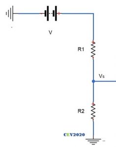
A basic voltage divider with appropriate resistor values can be used to scale down higher voltages V to microcontroller compatible levels, Vs.
Suppose readings are to be made in 0-50 V range. We need to scale down this 0-50 V range to 0-5 V.
Now current has to maintained as minimum as possible, to reduce errors. Let current be 0.5 mA. R1 should be of 100K range (5/0.5m). So,
As already stated, UNO has 10-bit resolution so voltage from 0 to 5V would be mapped into integers value from 0 to 1023, which is 5/1023 =4.88 mV per unit, which is fairly good accuracy.
The digital data from ADC can be easily used to manipulated to get the actual voltage, as follows:
GETTING LARGER RANGE
For a range of 500 V:
For current to be 0.5 mA, R1 should be of 1M range (500/0.5m). Thus,
Which is not a standard value so let R2 be 10K.
New scale is:
Putting the value of Vs:
DC CIRCUITS MEASUREMENTS
What we just did was for DC voltage measurement in 0-500V range.
AC CIRCUITS MEASUREMENTS
For AC measurement we have to make few modifications. As voltage range is only +ve (0 -5 V) so we need to either shift whole waveform above zero, or flip the negative cycle or simply chop it, and then take readings. Using suitable algorithms, AC values (RMS/ PEAK) could be found.
- READING RMS: Since UNO takes 100 usec for every reading. For a typical frequency of 50 Hz, a half-cycle consisting of 10 msec, so UNO can make 10m/100u or 100 readings. For these 100 readings, the formula to compute RMS can be applied as follows.
Sampling a half-sino, Image courtesy: Internet
- READING PEAK:
- Using sampling: Max value from the 100 readings from can be found out using some sorting algorithm and RMS can be simply computed from it.
- Using time-delay: Since peak occurs at t/4, so using a timer function to generate a time delay of 5 msec after zero crossing and then taking the reading would directly give the peak value.
Any of these three techniques can be used for AC measurement.
IMP: It might possibly be case that the waveform may not be crossing the zero when the ADC starts taking measurement case would result in wrong results or the ADC never captures the maxima case 2a will be faulty , to deal with this is to take a larger number of samples like 2000-3000 to reduce the probability of error occurring.
Sample code for case2a:
The above code can also be used to measure DC voltages.
The final circuit becomes:
Since the sample voltage can be directly fed to microcontroller so no conditioning is required. Let’s see is that the case for current measurement too???
CURRENT MEASUREMENTS
The underlying idea to measure current is to obtain proportional voltage samples for any given load current, read voltage value at ADC port and process the ADC output bit to get the current value.
A proportional voltage can be obtained simply by forcing the current through pure resistor. If the value of this resistor is extremely small compared to the load resistance the equivalent load impedance would hardly change thus load current remain the same and in turn a small but proportional voltage drop is obtained across the external resistance.
Assuming the load current range from 0-2 A. Keeping the external series resistance R, as small as 0.1Ω, the sample voltages will be in range of 0- 0.2 V i.e. (0 -200 mV).
Accuracy would be significantly compromised for small load current if this range of sample voltage is used at ADC.
GETTING LARGER RANGE
Here the sampled voltage requires a proper conditioning.
So, all we need to do is to boost up the sample voltage from 0-200 mV to 0-5 V range.
How would you do that???
Well this is a typical day-job in analog engineering. Technically this is called the signal amplification. Giving a signal a required gain to push the level to a higher value.
The Operational Amplifier
Let us just step back from the current project and take a dive to depths which is certainly not required as far as the project is concerned, but for the sake of spirit of learning more and better, in the name of love of subject. 🍹🍹
What are the Operational Amplifiers?
This class of devices singly forms the backbone of the modern analog industry. Just as the gates in digital electronics, the induction motor in power systems, the IC engine in mechanical systems, the library functions in the computer engineering field, these operational amplifiers are the basal workhorses of the modern analog systems. These little beasts are characterized by a versatile application, which includes amplifier, voltage source, current source, filters, actuator driver, comparator, etc.
The very first need for amplifier circuits typically appeared in long telephone lines to obtain proper signal conditioning at the receiving ends. The problem of the available amplifier in those days were their highly undependable gain due to the inherent nature of the active components used, vacuum tubes in 1930s and transistors after 1947. The gain varied enormously for small changes in working temperature and supply voltage. External condition like season, weather, humidity all of them made the gain of amplifier almost uncontrollable.
Harold Black, an electrical engineer at the bell laboratories in 1927 came up with a revolutionary technique that has now became so ubiquitous in all electronic circuit for control applications, it is called the negative feedback concept.
THE BIG IDEA: Use an amplifier made of undependable active elements to get a very large gain, typically infinite, and then use dependable passive element to provide negative feedback to it to obtain any reduced desired gain or transfer function.
This remarkable concept is the underlining principle of all the practical operational amplifiers used today.
Now to understand op-amp, as known popularly, there are two standpoints. One is this:
And the other is this:
And we have no doubt that you would like to understand it through the second stand point.
Now recall the first part of the basic idea i.e. building infinite gain op-amp, more or less this comes under the domain of pure analog electronics but given the versatility of operational amplifier the second part of basic idea, the design of negative feedback circuit using passive elements (resistors, capacitors, inductors) comes under the realm of the electrical engineering. Also, it largely deals with core electrical circuit theories like KVL, KCL, Thevenin’s, etc.
The first standpoint leads to accomplishment of first part of the basic idea, and the second stand-point leads to the realization of second part of the idea.
Now you would wonder how can we execute second part without knowing the first part, and here comes a great powerful tool to do this for you, it is the hack of all the complicated system around us.
“THE ABSTRACTIONS”
Without a solid-thorough understanding of how that horrendously intricate mesh of transistor and resistances work to produce infinite gain, we can still build a perfect negative feedback circuit to obtain exact desired transfer function (gain), using the abstractions.
This concept is so crucial and pervasive in building all modern perplexing systems the microcontrollers, computers, airplanes, particle accelerators, etc.
Consider this more striking example: the “printf” library function which we take for so granted, is an abstraction of the all the icky logics that goes into it to print a given string on some terminal or a display device. Try building your own function to print a string, you would be shocked at the complexity behind this little command.
The point is that we cannot keep on dwelling on basal stuffs if we wish to build something magnificent, if we do-we will never end up building an app, a website, a power converter, and so forth.
So, use of abstraction is a proven tool to reduce complexity, we can use this tool to derive some common results and build or understand large systems layer by layer.
What you see below is the abstraction of the mesh of transistor shown earlier.
WHAT DOES OP-AMP DO FOR US?
Well, they just simply produce output proportional to the difference in the voltage between the two input terminals. The proportionality constant is very high, order of 10^5, called the system gain, note Ed is in μV and o/p in V.
Mathematically,
The output characteristics for the device is as follows:
- The magnitude of output voltage depends on the difference between in the input terminal voltage in active region and it saturates once output hits the supply voltage magnitude.
- The polarity of output is same as the polarity of V+ wrt V-, thus V+ is called non-inverting terminal.
THE REAL OP-AMP
- The variety of op-amps available are many LM324, LM339, LM258, etc. Most popular is IC 741. In our project we will use LM358, as it is single supply dual op-amp, so it will reduce complexity a bit.
Image courtesy: ON Semiconductors
THE RULES OF OPERATION
- The difference in input voltage is very small (typically in μV) so the two input terminals can be assumed to be virtually shorted, i.e. at same voltage.
- The input impedance is very high, so both the input currents are zero.
- The gain is infinity.
This is all one need to know about op-amp, using these three rules op-amps can be used very easily to get required gain.
Let’s check it out.
ROUTINE EXAMPLES
Inverting configuration:
Just calmly apply the rules one by one.
- Input terminals at same voltage, so voltage at 2 is voltage at 1, i.e. zero.
- No current through input terminals. Apply KCL at terminal 2:
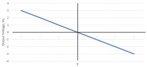
The characteristics become:
Non-inverting configuration:
Again, apply the same rules:
- Input terminals at same voltage, so voltage at 2 is voltage at 1, i.e. V1.
- No current through input terminals. Apply KCL at terminal 2:
The output characteristics become:
So, are you now able to appreciate the beauty of these curves we just obtained??? We began with an op amp with typically infinite gain (10^5), showing very creepy dependence on the temperature and external factors and here is a calm stable op-amp with desired finite gain by just using simple passive resistances.
New gain of system become (Rf/Rb) and (1+ Rf/Rb), which remains fairly constant for a wide temp range.
HOW THE NEGATIVE FEEDBACK WORKS?
Though equations obtained by reasonable mathematical approximations shows us independence of overall gain, but intuition is still lacking….
So, how does the results we just obtained is manifested actually????
So, lets simply heat an op-amp working in a non-inverting configuration, and see what happens.
As heating begins the gain begins to rise, and so does the output voltage. Corresponding to it there will be rise in voltage at terminal 2. Which would result in lowering the difference between the two input terminals, and consequently the output drops. This drop in output leads to drop in voltage at terminal 2 which results in increased differential voltage resulting in increased output. These oscillations die out soon and result is stable output displaying temperature independent gain. This is in general how a negative feedback principle works.
IMPORTANT
Ensure that the power is never off when the inputs and output are connected in the op-amp.
……………………………………….
So, it’s time to get back from where we left, the need to boost up the sample voltage from 0-200 mV to 0-5 V range.
Pretty cakewalk now, isn’t???
You would say it’s a lockdown. Where should I get the op-amp?
Cool, there are whole lot of gadgets and sensors where you can find it.
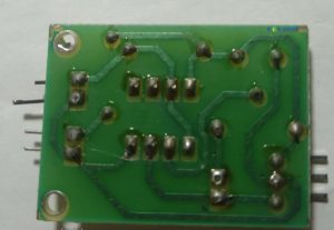
Say, for example, we extracted an op-amp from an IR sensor.
Due to unavailability of any solder iron, we just simply cut out the resistors, IR LEDs, POTs.
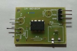 Using careful examination of the IC we traced out the whole IC circuit diagram.
And simply bought out the required terminals of op-amp by normal connectors.
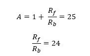
To boost the sample voltage from 0-200 mV to 0-5 V range, we need a gain of (5/200m = 25), since inverting is not desired hence using the non-inverting configuration.
Finally, we used pair of resistors in combination to get the required ohms and made the op-amp circuit with a gain of 24.6 as follows:
DC CIRCUITS MEASUREMENTS
What we finally got is a 0-5 V scale that would end up giving us 0-1023 integer, we have to get all the way back to current, lets gooooo!!!!!🚀🚀🚀🚀🚀
Analog Voltage at the ADC:
Voltage input to the non-inverting amplifier:
![]() Current through the external resistance:
Current through the external resistance:
 The overall conversion factor becomes:
AC CIRCUITS MEASUREMENTS
Contribute
FREQUENCY AND POWER FACTOR MEASUREMENT
Underdev
DISPLAY LCD
All about LCD interfacing with the Arduino can be very easily understood by referring this short 1 min read at Arduino.cc.
https://www.arduino.cc/en/Tutorial/LiquidCrystalDisplay
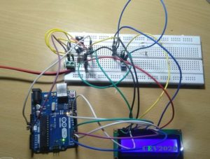
We tried the same, followed every step very accurately but unfortunately, results didn’t show up except this blank screen.
Help us to troubleshoot the problem by coming up with possible errors.
We build the icky circuit thrice from zero, and then checked and rechecked every connection, but failed.
MORAL:
- Life isn’t fair always, sometimes no matter how hard we try, no matter how dedicated our purpose is, we are destined to fail. We have realised this truth, and we hope to develop temperament to mindfully accept such failures in life.
- Connecting the circuit three times hadn’t yielded us the result, but surely planted in us the seed of perseverance to go through that nasty process. Surely, we raised our patience wall a little higher.
And it is these lessons and quality we wish to learn and develop by involving in these projects, not just simply putting things up.
THE FINAL CIRCUIT
Well do you think it’s done???
No, it’s not.
Since we are using same apparatus for the measurement of AC and DC. We hadn’t done anything to identify them. It can be done via program codes or by hardware.
By providing high or low manually on a digital pin we can indicate the microcontroller about it, say high for AC measurements and low for DC measurements.
THE FINAL CODES
#include <LiquidCrystal.h>
LiquidCrystal lcd(12, 11, 5, 4, 3, 2);

#define DCV_multiplier 0.499
#define DCC_multiplier 1.9531*10^-3

int read_voltage = A3;
int read_current = A4;
int select_pin = 7;
int voltage_adc_value = 0;
int current_adc_value = 0;
int voltage_peak_value = 0;
float dc_voltage= 0;
float ac_voltagerms= 0;
float dc_current = 0;
unsigned long sample_count = 0;

void setup()
{
  pinMode(A3, INPUT);
  pinMode (A4, INPUT);
  pinMode (7, INPUT);
  lcd.begin(16, 2);
  lcd.setCursor(0, 0);
  lcd.print("POWER MODULE");
  delay(3000);
  lcd.clear();
}

void loop()
{
  //Voltage Measurement//
  for(sample_count = 0; sample_count < 2000; sample_count ++)
  {
      voltage_adc_value = analogRead(read_voltage);
      if(voltage_peak_value < adc_value)
      voltage_peak_value = adc_value;
      else;
  }
      dc_voltage = voltage_peak_value * DCV_MULTIPLIER;
      ac_voltagerms = dc_voltage / 1.414;

  //Current measurement//
      current_adc_value = analogRead(read_current);
      dc_current = current_adc_value * DCC_MULTIPLIER;

  if ( select_pin==0 )
  {
      lcd.clear();
      lcd.setCursor(0, 0);
      lcd.print("DC SYSTEM");
      lcd.setCursor(0, 1);
      lcd.print(dc_voltage);
      lcd.print("V");
      lcd.print (" ");
      lcd.print (dc_current);
      lcd.print ("A");
 else
      lcd.print("AC SYSTEM");
      lcd.setCursor(0, 1);
      lcd.print(ac_voltagerms);
      lcd.print("V");
      delay(500);
  }
}
LOCKDOWN SPECIAL
We could arrange a low resistance of required power handling capacity, so current measurements cannot be made. Moreover, the resistors required for the voltage multiplier are also not available with us. So, we used op-amp to get the required gain, slight code modifications and obtained the results using the serial monitor. Battery voltage is 12.25 V power module shows 12.33 V, 0.65% error.
CONCLUSION
These power modules can be custom build for battery monitoring for systems like drones, etc. by removing AC measuring components and using small uC like Arduino NANO. They could be used for real-time monitoring of some load. They could be used to trigger some protective measures like triggering a relay, blowing a buzzer, etc. when any parameter beyond a limit.
The development or building of measurement systems is less about dwelling on rigorous electrical concepts rather more appropriately it could be categorized as a form of art, which requires small intuition of some very basic electrical phenomenon and rest is all about creativity to obtain the desired result by arranging the already available elementary elements.
If we could imagine force exerted on a wire carrying current in a magnetic field, if we can imagine emf induced in a changing magnetic field, if we can imagine magnetic field due to a coil carrying current, we are ready to go, about learning, understanding, modifying and building interesting measurement systems.
🍹🍹🍹
Keep reading, keep learning
AANTARAK DIVISION,
TEAM CEV!
References
- Special thanks to Prof Varsha Shah
- MIT OCW 6.002 Circuits and Electronics
- Mr Anand Aggarwal’s Fundamental of Analog and Digital Electronics
- Arduino.cc


