New Home

INTELLIGENT AUTOMATION

Reading Time: 4 minutes

– by Aastha Patel

CSE, Ist year
———–

WHAT IS INTELLIGENT AUTOMATION?

In simple words, Intelligent Automation (IA), can be defined as the unification of the two most widely-used technologies, Artificial Intelligence (AI) and Robotic Process Automation (RPA), to bring about the digital transformation and extend the automation process in the business industry.

In case you are wondering what automation is, it is the application of technology to maximize the efficiency of a process with minimum human intervention. It relies on the prescriptive instructions and the structured data inputs given by the humans. This traditional automation has been utilized by companies for a long time.

INTELLIGENT AUTOMATION
Intelligent Automation, IA = AI + RPA


WHAT ARE THE TECHNOLOGIES USED BY INTELLIGENT AUTOMATION?

Business Process Management (BPM) 

It ensures the efficient coordination of the people, system, and data. Its main objective is to provide a solid operational process for the business tasks that requires decision making, data generation, data exchanging, calculations, and storage from the beginning to the end.

Robotic Process Automation (RPA) 

The primary work of the RPA includes taking over repetitive tasks that have no exceptions, thereby reducing the human workload. This fast technology mainly replaces humans doing the simple work in business processes and that’s what makes it a robot. Due to this, people get more free time to focus on higher thinking skills and improve customer services.

Artificial intelligence (AI) 

I am sure most of you are aware of this technology. This has enabled us to create systems and machines that can think and self-learn just like us. It embraces many concepts like Machine Learning (ML), Natural Language Processing (NLP), Big Data, Deep Learning, etc. Machines can now decipher patterns, analyze data, perform predictive analysis, and can implement decision making from previous experiences. This is how our Netflix and Youtube recommendations work.

RPA can only handle back-end business functions, while Intelligent Automation can handle the complex front-end tasks too. Adding Intelligence and BPM to the RPA, can increase the automating of complex business tasks and contribute to the incredible workflow, thereby improving the productivity of the company. 


THE WORKING OF INTELLIGENT AUTOMATION

IA assists in the entire journey of automation, right from discovery to automation tasks to its optimization including all the front-end and back-end business complexities. 

Initially, it observes the work carried out by the people, analyzes and identifies the optimal workflow, and then proposes a path for automation of the business process using AI technology. 

Next, the AI tools are applied to the unstructured data including audio, video, and chat information to analyze the patterns in the data, reduce the repetitive tasks and make accurate predictions about productivity gains in the future.

Let’s take an example of emails and invoices to understand Intelligent Automation. The RPA is used for retrieving and downloading the files. On the other hand, AI is used to “read” the documents, extract the required information, and accordingly work upon it. The key advantages of using AI along with RPA, are accurate results and faster output with minimum human intervention.

In a nutshell, IA has expanded our abilities in Automation for the business process. 


BENEFITS OF INTELLIGENT AUTOMATION

  • Organizing Complex Data – IA stores, analyzes, manipulates, and retrieves the data from inputs and sources and runs appropriate processes on them.
  • Eliminating Errors – IA improves the accuracy of the complex tasks and with time reduces the exceptional errors caused by self-learning.
  • Reducing Operational Obstacles – It can operate on unstructured data, optimizes the human-digital workforce, and boosts up the productivity by giving consistent results.
  • Increasing Cybersecurity – Manages to address the potential threats to the security by analyzing the network of data.
  • Liberate Employees – It eliminates the repetitive tasks and hence the human concentration is shifted to thinking of innovative and creative tasks.

APPLICATIONS OF INTELLIGENT AUTOMATION

More than 80% of business firms are already using this technology. Due to this, they have observed a significant increase in their ROI (Return On Investment).

FINANCIAL SERVICES

The digital workers can handle almost all the tasks from transfers to payment processes. It can also help the customers in office reconciliation in the back-end and customer-experience in the front-end. 

HEALTHCARE SERVICES

Implementation of check-ups for surgery, record retention, post-surgery administration are some of the things that the IA is capable of, hence significantly reducing the manual processes and overhead costs.

TELECOMMUNICATION SERVICES

The IA offers great telecom services such as maintenance, installation, minimizing the downtime, and brings about customer satisfaction.

IA has succeeded in making our ideal Business Management a reality. The hybrid decisions of the human and the automation with intelligence have given a new definition to the digital transformation. It has proposed real solutions for our complex processes while simultaneously reducing our time, energy, and costs.


Thanks for reading, and will feel appreciated if followed by questions.

Keep reading, Keep learning.

Primer to HTML, CSS, BOOTSTRAP

Reading Time: 10 minutes

Landed here surfing through various amazing websites, wondering how they are designed?
Interested in front-end development, but just a beginner?
You are at the right place!
It’s never too late to start. So let’s get started.

1 Introduction to HTML, CSS and BOOTSTRAP

1.1 HTML

Hyper Text Markup Language was created by Tim Berners-Lee in 1991, is a markup language used for structuring and presenting content on Web.

  • Created to build the structure of the website.
  • Consists of several elements represented by tags.
  • These elements are rendered on the browsers in form of viewable content.

1.2 CSS

Cascading Style Sheets (CSS) is a simple language created to style the HTML elements.

  • Styling can be done using tag names, class names and id’s assigned to various elements in our HTML document.

Primer to HTML, CSS, BOOTSTRAP

1.3 BOOTSTRAP

Bootstrap is a very popular and useful framework of HTML, CSS and JS for creating responsive website designs.

  • It has inbuilt HTML, CSS based designs for different elements like button, divisions, images, lists, tables and many more; which can be directly used to create a responsive design very fast.


2 BOOTSTRAP basics

2.1 Bootstrap GRID

Bootstrap gridding system divides the page into 12 identical columns and multiple rows, which you can use to place HTML elements. More than 1 column(s) can be combined to achieve more width.
Primer to HTML, CSS, BOOTSTRAP

The gridding system consists of 4 classes:
xs – for screens less than 768px width
sm – for screens equal to or greater than 768px width
md – for screens equal to or greater than 992px width
lg – for screens equal to or greater than 1200px width

example:
<div class="row">
  <div class="col-sm-4">...</div>
  <div class="col-sm-8">...</div>
</div>

here you can verify there are two columns having a
span on 4 and 8 columns of the bootstrap grid system adding up to 12

2.2 Bootstrap classes

Contextual inbuilt classes can be used on different HTML elements to style them without having to write CSS code ourselves(you can assume that CSS is already written for the classes we are using). In this section we will discuss some important contextual classes provided by bootstrap.

  • Classes for div containers
    .container and .container-fluid are the bootstrap classes which can be assigned to a container div
    .container sets the division width less than screen width by rendering left and right margins.
    .container-fluid sets the division width= screen width.
    Primer to HTML, CSS, BOOTSTRAP
  • Classes for background color
    .bg-primary, .bg-success, .bg-info, .bg-warning, .bg-danger
    background color will automatically appear for the particular element when you assign any of these classes for it.Primer to HTML, CSS, BOOTSTRAP
  • Classes for text color
    .text-muted, .text-primary, .text-success, .text-info, .text-warning, .text-danger
    text color will automatically appear for the particular element when you assign any of these classes for it.
  • Classes for button
    .btn,.btn-default,.btn-primary,.btn-success,.btn-info,.btn-warning,.btn-danger,.btn-link
    button color will automatically appear for the particular button, when you assign any of these classes for it..btn-lg,
    .btn-sm,
    .btn-xs
    any of these classes when assigned to a button, resizes the button.
    Primer to HTML, CSS, BOOTSTRAP

These are some of the important classes we discussed. Bootstrap provides many more classes for many other elements. We will be using these classes and introduce other classes further.

2.3 Modifying style using CSS

After use of contextual classes that bootstrap provides, you might be feeling limited in no. of options. For example; for text coloring using class, the range of colors that bootstrap provides is very less (red(danger) ,yellow(warning) ,green(success) … etc). also, the other styling is very particular, like the button border, border-radius, font etc. The question is, do we have to work with these restrictions? This way, all the websites made using bootstrap will look identical with just changes in the content.
Primer to HTML, CSS, BOOTSTRAP
Fortunately this doesn’t happen. We can do all types of styling changes using CSS. We just have to assign a different class(not bootstrap classes) to the target element and set/update any CSS property of our choice. The CSS will be rendered on the target element.

example:

<div class="container">
<p>we are modifying CSS of a button.</p>
<button class="btn btn-lg btn-danger colorchange"></button>
</div>

<style>
.colorchange{
  background-color: #000000;
  border-radius: 20px;
}
.colorchange:hover{
  background-color: green;
  transition:0.7s;
}
</style>


After a brief intro to the languages and frameworks we will be using further and learning bootstrap basics, lets get our hands on and start making a beautiful static responsive website.


3 Let’s start building 😉

Prerequisites
  • Basics of HTML and CSS
  • Some theory about bootstrap that we discussed above

3.1 Setting up environment to start off

Directory structure will be like-

Project folder

  • index.html
  • style.css
  • assets folder (containing images to be used)

To start off, all you need is a text editor. I prefer Brackets text editor because it comes along with autocomplete feature, which saves time and I’ll be using Brackets throughout. There are several alternatives to brackets like sublime text editor, atom etc.

Another requirement to start off is Bootstrap.

  • You can download it from getbootstrap.com
  • or you can use bootstrap CDN(which I’ll be doing).
  • NOTE: If you use CDN, internet connection will be needed for bootstrap to do the rendering.
<link rel="stylesheet" href="https://maxcdn.bootstrapcdn.com/bootstrap/3.4.1/css/bootstrap.min.css">
<script src="https://ajax.googleapis.com/ajax/libs/jquery/3.4.1/jquery.min.js"></script>
<script src="https://maxcdn.bootstrapcdn.com/bootstrap/3.4.1/js/bootstrap.min.js"></script>
  • another font-awesome CDN is to be included in our html file. The various icons that we will include in our website(in following sections) uses this.
<link rel="stylesheet" href="https://cdnjs.cloudflare.com/ajax/libs/font-awesome/4.7.0/css/font-awesome.min.css">

you can copy these CDNs in the head tag.

Setting up
index.html to begin.

<html>
   <head>
     <meta charset="utf-8">
     <meta name="viewport" content="width=device-width, initial-scale=1">
     <link rel="stylesheet" href="https://maxcdn.bootstrapcdn.com/bootstrap/3.4.1/css/bootstrap.min.css">
     <script src="https://ajax.googleapis.com/ajax/libs/jquery/3.4.1/jquery.min.js"></script>
     <script src="https://maxcdn.bootstrapcdn.com/bootstrap/3.4.1/js/bootstrap.min.js"></script>
     <link rel="stylesheet" href="https://cdnjs.cloudflare.com/ajax/libs/font-awesome/4.7.0/css/font-awesome.min.css">
     <link rel="stylesheet" href="./style.css">
     <title>
       My first Bootstrap Template.
     </title>
   </head>
   <body>

   </body>
   </html>

meta tag is used for proper zooming and rendering during the first load of the page on browser. Test run index.html once. Now we have set up the environment required for making our website.
Don’t forget to link your CSS file to this in head tag.

3.2 Making different sections

The sections we will be building will be:

  • HOME
  • GALLERY
  • TEAM
  • CONTACT

Now, I’ll provide you the source code used. Notice the Bootstrap classes being used. Also watch the styling changes that I’m making in the CSS file to change the designs of the target elements. All sections here, are child elements of body tag. You can use my source code given below. Feel free to work around with your own ideas and tweaking.

HOME

This section will contain the page which first loads on user’s screen. This will contain Logo, Menu, Text in middle, Background image.

Primer to HTML, CSS, BOOTSTRAP
index.html:

<div class="container-fluid home" id="home">

            <nav class="navbar">
                <div class="container">
                    <div class="navbar-header">
                        <a class="navbar-brand" href="#">LOGO</a>
                    </div>
                    <ul class="nav navbar-nav navigation" >
                        <li><a href="#home">HOME</a></li>
                        <li><a href="#gallery">GALLERY</a></li>
                        <li><a href="#team">TEAM</a></li>
                        <li><a href="#contact">CONTACT</a></li>
                    </ul>
                </div>
            </nav>

            <div class="row">
                <div class="col-sm-3"></div>
                <div class="col-sm-6">
                    <h1>QUOTE:</h1>
                    <H3>"Dreams of great dreamners are always transcended,<br><br> - A.Kalam"</H3>
                </div>
                <div class="col-sm-3"></div>
            </div>
        </div>

style.css:

.home{
    background-image: linear-gradient(rgba(0,0,0,.6),rgba(0,0,0,.6)),url(https://wallup.net/wp-content/uploads/2018/09/25/607518-leaves-dark-macro-water_drops-camera-748x421.jpg);
    background-size: cover;
}
.home .row{
    margin-top: 10%;
    margin-bottom: 15%;

}
.navbar{
    margin-top: 5%;
}
.navbar ul{
    float: right;
}
.nav li{
    border-bottom: 1px solid whitesmoke;
    text-align: center;
}
.navbar-brand{
    color: white;
    border: 1px solid white;
    border-radius: 50px;
}
.nav li a:hover{
    color: black;
}
.nav li a{
    color: white;
}

.home .row h1{
    color: cadetblue;
    margin: 50px;
    margin-left: 0;
    border-bottom: 1px solid cadetblue;
}

.home .row h3{
    color: white;
    margin: 30px;
}


GALLERY

This section in our page will contain an image carousel with left and right swipe controls to view different images of gallery.
Primer to HTML, CSS, BOOTSTRAP

index.html

<div class="container-fluid gallery" id="gallery">
            <div class="container-fluid">
                <h1>Gallery</h1>
                <center><p>Galleries are pages which contain large numbers of media content—almost always, images—with little or no supporting
                text. Large numbers of galleries have been deleted from Wikipedia per WP:NOT. This is usually cited in this context as
                WP:NOT an image gallery, which is a paraphrase of the official policy that Wikipedia articles are not mere collections
                of photographs or media files. There are, therefore, very few gallery-articles left on Wikipedia in the main article
                namespace (see [1]). This page defines how, when, and where gallery-articles should and should not be used. It is not
                concerned with the use of the gallery feature within pages that are predominantly text-based articles</p></center>
                <div id="myCarousel" class="carousel slide" data-ride="carousel">
                    <!-- Indicators -->
                    <ol class="carousel-indicators">
                        <li data-target="#myCarousel" data-slide-to="0" class="active"></li>
                        <li data-target="#myCarousel" data-slide-to="1"></li>
                        <li data-target="#myCarousel" data-slide-to="2"></li>
                    </ol>

                    <!-- Wrapper for slides -->
                    <div class="carousel-inner">
                        <div class="item active">
                            <center><img src="https://hrexecutive.com/wp-content/uploads/2018/10/GettyImages-869538734broken700-700x450.jpg"></center>
                        </div>

                        <div class="item">
                            <center><img src="https://kubesystems.com/wp-content/uploads/2016/05/bg-dark-3-700x450.jpg"></center>

                        </div>

                        <div class="item">
                            <center><img src=""></center>  
                        </div>
                    </div>

                    <!-- Left and right controls -->
                    <a class="left carousel-control" href="#myCarousel" data-slide="prev">
                        <span class="glyphicon glyphicon-chevron-left""></span>

                    </a>
                    <a class="right carousel-control" href="#myCarousel" data-slide="next">
                        <span class="glyphicon glyphicon-chevron-right""></span>

                    </a>
                </div>

            </div>
        </div>

style.css

/*GALLERY*/
.gallery{
    background-color: black;
}
.gallery .container-fluid{
    margin-top: 100px;
    margin-bottom: 60px;
    background-color: url(https://wallup.net/wp-content/uploads/2018/09/25/607518-leaves-dark-macro-water_drops-camera-748x421.jpg);
}
.gallery h1{
    padding-bottom: 30px;
    margin-bottom: 20px;
    border-bottom: 1px solid white;
    color: white;
    font-weight: lighter;
    text-align: center;
}
.gallery .item{
    text-align: center;
}
.gallery .item img{
    text-align: center;
}
.gallery p{
    text-align: center;
    width: 70%;
}


OUR TEAM

This section of our page will display 3 team members in form of cards. The cards will contain personal information about each member.
Primer to HTML, CSS, BOOTSTRAP

index.html

<div class="container-fluid team" id="team">
            <div class="container">
                <h1>Our Team</h1>

            <div class="row">
                <div class="col-sm-4">
                    <center>
                        <div class="shift s1">
                            <img src="https://biobaseddelta.com/wp-content/uploads/2018/08/person-450x340.jpeg" />
                            <h3>Member 1</h6><span>Designation</span><br><br>
                            <i class="fa fa-facebook"></i><i class="fa fa-twitter"></i><i class="fa fa-google-plus"></i><i
                                class="fa fa-instagram"></i>
                            <center>
                                <p>
                                    A team is a group of individuals (human or non-human) working together to achieve their goal.

                                    As defined by Professor Leigh Thompson of the Kellogg School of Management, "[a] team is a group of people who are
                                    interdependent with respect to information, resources, knowledge and skills and who seek to combine their efforts to
                                    achieve a common goal".[1]
                                    Team members need to learn how to help one another, help other team members realize their true potential, and create an
                                    environment that allows everyone to go beyond their limitations.[4]
                                </p>
                            </center>
                        </div>
                    </center>
                </div>

                <div class="col-sm-4">
                    <center>
                        <div class="shift s1">
                            <img src="https://biobaseddelta.com/wp-content/uploads/2018/08/person-450x340.jpeg" />
                            <h3>Member 1</h6><span>Designation</span><br><br>
                                <i class="fa fa-facebook"></i><i class="fa fa-twitter"></i><i class="fa fa-google-plus"></i><i
                                    class="fa fa-instagram"></i>
                                <center>
                                    <p>
                                        A team is a group of individuals (human or non-human) working together to achieve their goal.

                                        As defined by Professor Leigh Thompson of the Kellogg School of Management, "[a] team is a group
                                        of people who are
                                        interdependent with respect to information, resources, knowledge and skills and who seek to
                                        combine their efforts to
                                        achieve a common goal".[1]
                                        Team members need to learn how to help one another, help other team members realize their true
                                        potential, and create an
                                        environment that allows everyone to go beyond their limitations.[4]
                                    </p>
                                </center>
                        </div>
                    </center>
                </div>
            </div>
        </div>
        </div>

style.css

/*TEAM*/
        .shift{
           text-align: center;
           background-color: #fff;
           padding: 30px;
           margin-top: 30px;
           margin-bottom: 50px;
           width: 100%;
           position: relative;
       }
       .shift .row{
           margin-top: 50px;
           margin-bottom: 50px;
       }
       .team h1{
           text-align: center;
           border-bottom: 1px solid black;
           margin: 30px;
       }
       .shift:hover{
           box-shadow: 0 4px 8px 0 rgba(0, 0, 0, 0.2), 0 6px 20px 0 rgba(0, 0, 0, 0.19);
       }
       .shift i{
           font-size: 0;
           padding: 0;
           margin-left: 5px;
           margin-right: 5px;
           border-radius: 60px;
           visibility: hidden;

       }
       .s1:hover > i{
           visibility: visible;
           font-size: 17;
           padding: 8px;
           border: 1px solid white;
           transition: 0.3s;  
       }
       .team img{
           text-align: center;
           width: 50%;
           height: auto;
       }
       .team p{
           width: 90%;
       }


CONTACT

This section will contain a contact form (made using form tag) and other contact details. At the end of the page there is a simple footer section.
Primer to HTML, CSS, BOOTSTRAP

index.html

<div class="container-fluid contact" id="contact">
    <div class="container">
        <h1>Contact</h1>
        <div class="row">
        <div class="col-sm-6">
            <h2>Get In Touch</h2>
            <form>
                <input type="text" placeholder="Your Name" required><br>
                <input type="email" placeholder="Your eMail" required><br>
                <input type="number" placeholder="Your Contact No." required><br>
                <textarea></textarea>
                <button type="submit" class="btn btn-primary x">Send Message</button>
            </form>
        </div>
        <div class="col-sm-1"></div>
        <div class="col-sm-5">
            <h4>EMAIL</h4>
            probootstrap@gmail.com<br><br>
            <h4>PHONE</h4>
            +30 976 1382 9921<br><br>
            <h4>FAX</h4>
            +30 976 1382 9922<br><br>
            <h4>ADDRESS</h4>
            San Francisco, CA<br>
            4th Floor8 Lower<br>
            San Francisco street, M1 50F<br>
        </div>
        </div>
    </div>
</div>
<div class="container-fluid foot">
    <i class="fa fa-twitter" aria-hidden="true"></i>
    <i class="fa fa-facebook" aria-hidden="true"></i>
    <i class="fa fa-instagram" aria-hidden="true"></i>
    <i class="fa fa-linkedin" aria-hidden="true"></i><br><br>
    © 2020.<br>
    Designed by: Shreyash .K<br>
    Demo bootstrap template.
</div>

style.css

/*CONTACT*/
.contact{
    background-image: linear-gradient(rgba(0,0,0,.7),rgba(0,0,0,.7)),url(https://www.pixelstalk.net/wp-content/uploads/images2/Free-Hd-Dark-Wallpapers-Images.jpg);
    background-size: cover;
}
.contact .container h1{
    color: white;
    text-align: center;
    border-bottom: 1px solid white;
}
.contact .container h2{
    color: silver;
}
.contact .container{
    margin-top: 50px;
    margin-bottom: 25px;
}
.contact form{
    background-color: silver;
    padding: 20px;
    border-radius: 10px;
}
.contact .row{
    margin-top: 50px;
}
.contact form input{
    width: 100%;
    margin: 10px;
    margin-left: 0;
    height: 25px;
}
.contact form textarea{
    width: 100%;
    height: 20%;
}
.contact form button{
    background-color: black;
    margin: 5px;
}
.contact .col-sm-5{
    color: silver;
}
.foot{
    text-align: center;
    padding: 25px;
    background-color: black;
    border-top: 1px solid white;
}
.foot i{
    color: white;
    padding: 5px;
}
.foot i:hover{
    background-color: white;
    color: black;
    transition: 0.4s;
}


And our first bootstrap website design is ready!
Hope you enjoyed it. You can now create more such designs using even more variety of elements and classes provided by bootstrap. Try experimenting different combinations of styling and make your design attractive to the viewer.
Thank you!
keep learning, keep growing.

YANTRIKA DIVISION,

TEAM CEV.

Building Code

Reading Time: 5 minutes

What is Building Code?

The Building Code is an instrument providing guidelines for regulating the building construction activities across the country. Building codes are generally intended to be applied by architects, engineers, interior designers, constructors, and regulators but are also used for various purposes by safety inspectors, real estate developers, and others. Codes that regulate the design and construction of structures were adopted into law.


Why Building Code?

A building code (also building control or building regulations) is a set of rules that specify the standards for constructed objects such as buildings and non-building structures. Buildings must conform to the code to obtain planning permission, usually from a local council. The primary purpose of building codes is to protect public health, safety, and general welfare as they relate to the construction and occupancy of buildings and structures. The building code becomes the law of a particular jurisdiction when formally enacted by the appropriate governmental or private authority.


History of Building Code

King Hammurabi enacted the first known written building code in Babylon in 1758 B.C. written in stone. The code doesn’t have a guideline on how to work and what steps to use. Instead, it states that “If a builder has built a house for a man and his work is not strong, and if the house he has built falls in and kills the householder, that builder shall be slain.”

After the great fires in London in 1666 and Chicago in 1871, building codes started addressing the risks one building posed to adjacent buildings and the public. Denser development in cities, and hazards associated with proximity and taller buildings, led to regulations for the construction of common walls between buildings and outlawing dangerous practices like wooden chimneys. Problems in existing buildings led to codes for light and ventilation, fire escapes, toilets and sanitary drains, and stairs and railings.

In 1905, the US organization, the National Board of Fire, created the first National Code to minimize risk.  By 1940, the United States had three regional code organizations, each with its own code. These three organizations and their codes were consolidated into the International Code Council (ICC), and the first set of “I-codes” was published in 2000. These codes include the International Building Code (IBC), the International Residential Code (IRC), the International Energy Conservation Code (IECC), as well as mechanical, plumbing, fire and other codes.


Types & Classification of the current building structure

There are instances when some local jurisdictions choose to develop their own building codes. A long time ago, all major cities in the United States had their own building codes. However, due to the ever-increasing complexity and cost of developing building regulations, virtually all municipalities in the country have chosen to adopt model codes instead. For example, in 2008, New York City abandoned its proprietary 1968 New York City Building Code in favor of a customized version of the International Building Code. The City of Chicago remains the only municipality in America that continues to use a building code the city developed on its own as part of the Municipal Code of Chicago.

In Europe, the Eurocode is a pan-European building code that has superseded the older national building codes. Each country now has National Annexes to localise the contents of the Eurocode.

Similarly, in India, each municipality and urban development authority has its own building code, which is mandatory for all construction within their jurisdiction. All these local building codes are variants of a National Building Code, which serves as model codes providing guidelines for regulating building construction activity.


Classification

Under the building code, constructed building or newly built structures can be classified on the following basis-

  • Use and Occupancy
  • Types of Construction

Use and Occupancy

The IBC has ten main occupancy groups as well as multiple subgroups.  The occupancy group or subgroup defines the specific use of the building. Subgroups are numbered based on the perceived risk for the building occupants.  The lower the subgroup number, the higher the perceived threat.

In many cases, a building has space that may be classified under more than one occupancy group.  These multi-use buildings are identified as a Mixed occupancy type.  However, if a building space can be considered as either an Accessory occupancy or an Incidental Use area, it may become part of the leading occupancy group.

Occupancy type determines the vertical live loading requirements for the building structure.  For higher-risk buildings such as a fire station, school, or theatre, lateral loads (e.g. wind and seismic) and snow will require increases to the loading requirements.

OCCUPANCY GROUP

SUBGROUPS

USES INCLUDE

Assembly

Groups A-1, A-2, A-3, A-4, & A-5

Gatherings –  civic/religious/social/recreational

Business

Group B

Office/Professional or Service  Transactions

Educational

Group E

K-12 Schools (some Daycare)

Factory/Industrial

Groups F-1 & F-2

Manufacturing/Fabrication/Packaging

High Hazard

Groups H-1, H-2, H-3, H-4, & H-5

Hazardous Materials

Institutional

Groups I-1, I-2, I-3, & I-4

Assisted Living/Hospitals/Prisons

Mercantile

Group M

Display & Sale of Merchandise

Residential

Groups R-1, R-2, R-3, & R-4

Housing/Apartments/Hotels

Storage

Groups S-1 & S-2

Non or Low-Hazardous Storage  (including parking garages)

Utility & Miscellaneous

Group U

Accessory Structures

Construction Type

Construction Type identifies the type of materials utilised for constructing a building and classifies the level of combustibility and fire resistance associated with the building elements of a structure. These building elements are required to have a fire-resistance rating of 0, 1, 2, or 3 hours, which indicates the amount of time it can continue to confine a fire and also maintain a level of structural integrity.

Table 601 of the IBC* identifies the fire-resistance requirements of building elements for the five construction types:

  • Types I and II – All building elements are of non-combustible materials.
  • Type III – Exterior walls are of non-combustible materials or fire-retardant wood framing with a 2-hour fire rating or less and interior building elements are of any code permitted materials, combustible or non-combustible.
  • Type IV – Heavy Timber (HT) construction.  Exterior walls are of non-combustible materials or fire-retardant wood framing with a 2-hour fire rating or less, and interior building elements are of unconcealed solid or laminated wood members that meet minimum dimension requirements required by the code.
  • Type V – Structural elements, exterior walls, and interior walls are of any materials permitted by the code, combustible, or non-combustible.

For construction types I, II, III, and V, structural building elements must also be classified as either A or B, resulting in a total nine kinds (i.e. Types IA, IB. IIA, etc.):

  • A = Protected – Structural members have additional fire rating coating or cover using spray-on, sheetrock, or other approved method that increases the fire-resistance rating by at least 1-hour.
  • B = Unprotected – Structural members have no additional coating or cover.


References

https://en.wikipedia.org/wiki/Building_code

https://www.motherearthnews.com/green-homes/building-codes-zmaz06djzraw

https://www.buyerschoiceinspections.com/history-of-building-codes

https://evstudio.com/classification-of-work-and-scope-in-the-existing-building-code/

https://www.nishkian.com/how-are-buildings-and-structures-classified-in-the-current-building-code/

https://study.com/academy/lesson/building-ordinances-codes-definition-types-purpose.html

Customer Service in any Organization

Reading Time: 6 minutes

AUTHOR: SUKESH MATHUR

For any profit-based organization, it is often said, “Excellent customer service is the number one job in any company. It is the personality of the company and the reason customers come back. Without customers, there is no company.” This belief has helped many companies achieve success in their respective fields and in this blog I have discussed what really is Customer Service and share my experience of more than 30 years in the field.

So, product service is basically the provision of support (service) to the customer before, during, and after the purchase of the product. Whatever be the situation, the employees of the organization have to adjust themselves to the varying personalities of the customer to ensure success in the field of customer service and the overall success of the company. An organization that values customer service has to spend more resources on training employees/customers than an average organization.

Customer Service in any Organization

An important mantra that any organization should follow while training their employee is that they should believe in proactive customer service rather than reactive customer service. Proactive Customer Service refers to effective planning earlier to tackle all the situations customers put you in. Whereas, reactive customer service refers to acting spontaneously to the complaints of the customer. This often causes a panic situation in the company causing many extreme steps that could further affect the reputation of the organization. 


Role of Customer Service in any Business

Contrary to common misconception, Customer Service also plays a vital role in the overall sales process of the organization and generating revenue of the organization as in today’s industry a lot depends on the reputation of the company. Due to this perspective, customer service should be included as a part of the overall approach of the systematic improvement of the company. It is important to understand that even one good customer service provided can change the entire perception of the customer towards the company.

Customer Support doesn’t limit to just solving a client’s problems with the product. Once the customer buys the product from the organization, it is the organizations’ prime duty to help the customer that he/she uses the product right and cost-effective. To ensure this, the organization has to assist the customer in planning, installation, training, troubleshooting, maintenance, upgrading, and disposal of the product.


Customer Complaint Registration Process

Customer Service may be provided by a person (eg. service or sales representative) or by automated means such as digital kiosks, web sites, and mobile applications.

In the case of a person, a service representative is assigned for taking the complaint directly from the customer. He is basically the point of contact with the consumer for the company. He takes complaints from the customer and assigns the same to the concerned service engineer. The service representative ensures continuous feedback to the customer on the status of his/her complaint until the resolution of the complaint and subsequent feedback to the company from the customer. This has been the go-to mode of customer service for many years but the disadvantage of the method is the time constraint and difficulty in communication between many layers. But these problems are now getting minimized with the help of Automated Customer Service.

One of the advantages of Automated means is an increased ability to provide 24 * 7 hours service, which highly compliments with customers’ needs. Also, customer service is becoming data-driven. So these automated methods could be really helpful. Some of the most popular types of Automated Customer Service are :

i) Artificial Intelligence

ii) Touch-Tone Phone

iii) Online Commerce (Websites)


i) Artificial Intelligence

AI customer service technologies can highly reduce the workload of customer service representatives as it solves minor and some major frequent issues easily. Customers can visually interact with the company’s model and solve their complaints at their own level with the help of proper technology.

Two of the most significant ways AI is augmenting customer service is through AI-augmented messaging and AI email tagging. AI-augmented messaging enables customer service agents to handle a big part of customer queries with the help of chatbot assistants.

Customer Service in any Organization

ii) Touch-Tone Phone

Touch- Tone Phone refers to the customer service dealt with an augmented machine voice that interacts with the customers. It usually involves IVR (Interactive Voice Response), the main menu, and uses the keypad as options to react according to customer’s needs. You might have come across them when you dial mobile connection customer service. (Press 1 for English, 2 for Hindi!)

Customer Service in any Organization

iii) Online Commerce

In the present era organizations are enhancing and maintaining personal experience using the advantages of online commerce. Online customers are invisible and not connected directly which makes it very difficult to effectively communicate with them. Also due to this invisibility, it makes it even more crucial for the organization to create a sense of personal human to human connection. Artificial means of service enables the companies to provide automated online assistants to customers through websites. These methods highly reduce the operating and training costs for the organizations.


Measurement of Customer Service Result

It is very important to keep in check the service provided by the company to the customers and hence Measurement of Customer Service Result is very crucial. Customer Service could be measured in the following ways:- 

i) First Response Time

ii) Restoration Time

i) First Response Time

This indicates how fast an organization responds to the complaints registered by the customer. To ensure minimum response time, an organization must have sufficient manpower for engineers and technicians. Without manpower, it is very difficult to maintain a good first response time which further affects the company.

ii) Restoration Time

Once the response is provided, restoration time is the time by which the customer complaint is completely resolved. To ensure minimum restoration time, the company must have Trained and Manpower and Sufficient stock of Spare Parts.

If the engineer gives a prompt response to the customer’s complaint but he is not well trained by the organization on the product, he/she would be unable to understand the customer complaint and act on it. Hence the restoration time sways away from the target time. Again if a response is given and the engineer is well trained, but if no spare parts are required to solve the complaint’s problem, the restoration time is affected. So have a proactive customer service, the organization should always be well prepared. I have seen all types of situations and it is very important to be in constant touch with time.


Customer Satisfaction (CSAT)

 This term is frequently used by the marketing team of the company. It is a measure of how products supplied and services rendered to the customer has achieved or crossed the customer expectations. Customer satisfaction is defined as the number of customers or percentage of total customers, whose reported experience with the company, its products, or its service index exceeds specified satisfaction goals.

In marketing, the managers found customer satisfaction measuring system very useful in managing and monitoring their business. It is observed as a key performance indicator within business and is also a part of the scorecard analysis of the company. 

In today’s competitive world, customer satisfaction is seen as a key differentiator and increasingly has become a key element of business strategy. In a nutshell, Customer Service or Product Service has been a key industry for the past many years and with the advancements in current technology, customer service will find a new path but the score would remain the same.

Customer Service in any Organization

A Power Module

Reading Time: 17 minutesSpecial Thanks to

  1. Prof Varsha Shah, EE Dept, SVNIT
  2. Mr Anand Aggarwal’s 6.002 MIT OCW Course 

Above is a team of thousands of different power modules, better known as the control room of a power plant.🦾

Are you ready to know one of them???

INTRODUCTION

Control and measurement of system parameters is a crucial facet for reliable and safe operation of any electrical systems, particularly for real-time system. By real-time system we mean the system whose parameters like current, voltage, impedance, power, etc. changes with time, thus to maintain the parameters under threshold limits, we first require to monitor them i.e. take measurements in real-time.

For most of the electrical circuits, the voltages and currents are two parameters of greatest interest, as they are solely responsible for safe operation. When unchecked one leads to electrical breakdown and another a thermal breakdown.

Consider the following cases:

  1. A battery backup system, constant monitoring of battery terminal voltage is necessary to stop the battery from getting over-discharged. Also, current drawn has to be monitored to check that the battery doesn’t overheats and catch flames.
  2. In the power system, bus voltages and currents in line have to be maintained very precisely, which again requires first taking measurements.
  3. For metering of electrical energy consumed by a consumer, we need voltage, current and power factor measurement.
  4. Majority of control systems in industrial system employ a negative feedback technique which essentially requires sampling/monitoring of a particular output parameter, which is itself a form of measurement.

PREREQUISITES

KVL and KCL, 😅😅 rest leave on us!!!

THE PROJECT IN SHORT:

Under this project, we set out to build a dynamic power module for measurement of current and voltage in DC circuits and current, voltage, power factor and frequency in AC systems in real-time to constantly monitor them and trigger necessary safeguards.

It’s pretty obvious that real-time operations are best executed with the help of microcontrollers. Microcontrollers are equipped with a group of pins called ADCs which basically read analog voltage level and convert them to n-bit digital data. Problem is that these microcontrollers can hardly survive above 5 V pressure.

So, if we wish to measure higher AC/DC values then we are required to take proper samples of voltage and current, then do proper conditioning, and finally process the data to compute the parameters.

ARDUINO UNO and ADC

With first boards appearing in 2005, Italy based Arduino.cc is open-source software and hardware company which gives a range of affordable microcontroller. With a broad computational power range, they are easy to use platform for purposeful use in industry, education, art etc.

A Power Module

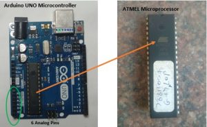
Atmel based Arduino UNO introduced in year 2010 with 32KB of flash memory is best suited to serve the purpose for this module.

Now we are interested in ADC function, for that Arduino UNO has following specifications:

A Power Module

The meaning of these specifications is:

“UNO contains 6, 10-bit channels for analog to digital conversion. It maps analog input voltage at these pins from 0-5 V into integer values between 0- 1023, yielding a resolution of 5V/1024 or 4.8828 mV/unit. It takes 100 usec to read one input, so max reading speed is 10000 times a second.”

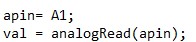
Syntax assigned is analogRead(pinname). It reads pin “pinname” and returns 10-bit int accordingly.

Sample code:

A Power Module

ADC DISCRPTION AVIALABLE AT ARDUINO.CC

https://www.arduino.cc/reference/en/language/functions/analog-io/analogread/

VOLTAGE MEASUREMENT

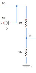
A basic voltage divider with appropriate resistor values can be used to scale down higher voltages V to microcontroller compatible levels, Vs.

A Power Module

A Power Module

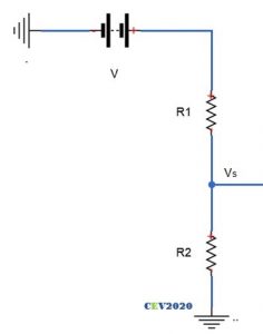
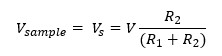
Suppose readings are to be made in 0-50 V range. We need to scale down this 0-50 V range to 0-5 V.

A Power Module

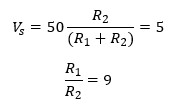
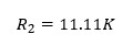
Now current has to maintained as minimum as possible, to reduce errors. Let current be 0.5 mA. R1 should be of 100K range (5/0.5m). So,

A Power Module

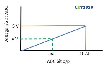
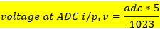
As already stated, UNO has 10-bit resolution so voltage from 0 to 5V would be mapped into integers value from 0 to 1023, which is 5/1023 =4.88 mV per unit, which is fairly good accuracy.

A Power Module

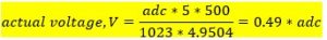
The digital data from ADC can be easily used to manipulated to get the actual voltage, as follows:

A Power Module

GETTING LARGER RANGE

For a range of 500 V:

A Power Module

A Power Module

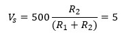
For current to be 0.5 mA, R1 should be of 1M range (500/0.5m). Thus,

A Power Module

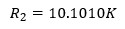
Which is not a standard value so let R2 be 10K.

New scale is:

A Power ModuleA Power Module

A Power Module

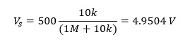
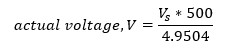
Putting the value of Vs:

A Power Module

DC CIRCUITS MEASUREMENTS

What we just did was for DC voltage measurement in 0-500V range.

AC CIRCUITS MEASUREMENTS

For AC measurement we have to make few modifications. As voltage range is only +ve (0 -5 V) so we need to either shift whole waveform above zero, or flip the negative cycle or simply chop it, and then take readings. Using suitable algorithms, AC values (RMS/ PEAK) could be found.

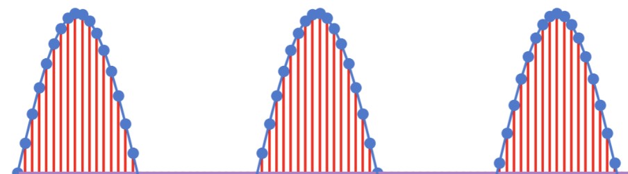
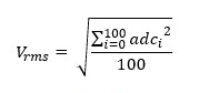
  1. READING RMS: Since UNO takes 100 usec for every reading. For a typical frequency of 50 Hz, a half-cycle consisting of 10 msec, so UNO can make 10m/100u or 100 readings. For these 100 readings, the formula to compute RMS can be applied as follows.

A Power Module

A Power Module

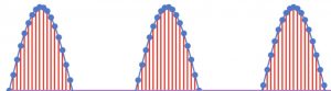
Sampling a half-sino, Image courtesy: Internet

  1. READING PEAK:
    1. Using sampling: Max value from the 100 readings from can be found out using some sorting algorithm and RMS can be simply computed from it.
    2. Using time-delay: Since peak occurs at t/4, so using a timer function to generate a time delay of 5 msec after zero crossing and then taking the reading would directly give the peak value.

Any of these three techniques can be used for AC measurement.

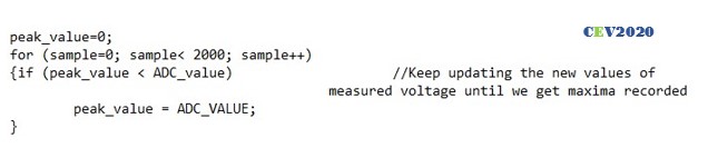
IMP: It might possibly be case that the waveform may not be crossing the zero when the ADC starts taking measurement case would result in wrong results or the ADC never captures the maxima case 2a will be faulty , to deal with this is to take a larger number of samples like 2000-3000 to reduce the probability of error occurring.

Sample code for case2a:

A Power Module

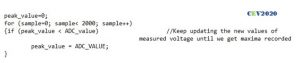
The above code can also be used to measure DC voltages.

The final circuit becomes:

A Power Module

Since the sample voltage can be directly fed to microcontroller so no conditioning is required. Let’s see is that the case for current measurement too???

CURRENT MEASUREMENTS

The underlying idea to measure current is to obtain proportional voltage samples for any given load current, read voltage value at ADC port and process the ADC output bit to get the current value.

A proportional voltage can be obtained simply by forcing the current through pure resistor. If the value of this resistor is extremely small compared to the load resistance the equivalent load impedance would hardly change thus load current remain the same and in turn a small but proportional voltage drop is obtained across the external resistance.

A Power Module

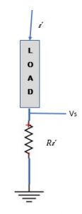
Assuming the load current range from 0-2 A. Keeping the external series resistance R, as small as 0.1Ω, the sample voltages will be in range of 0- 0.2 V i.e. (0 -200 mV).

Accuracy would be significantly compromised for small load current if this range of sample voltage is used at ADC.

GETTING LARGER RANGE

Here the sampled voltage requires a proper conditioning.

So, all we need to do is to boost up the sample voltage from 0-200 mV to 0-5 V range.

How would you do that???

Well this is a typical day-job in analog engineering. Technically this is called the signal amplification. Giving a signal a required gain to push the level to a higher value.

The Operational Amplifier

Let us just step back from the current project and take a dive to depths which is certainly not required as far as the project is concerned, but for the sake of spirit of learning more and better, in the name of love of subject. 🍹🍹

What are the Operational Amplifiers? 

This class of devices singly forms the backbone of the modern analog industry. Just as the gates in digital electronics, the induction motor in power systems, the IC engine in mechanical systems, the library functions in the computer engineering field, these operational amplifiers are the basal workhorses of the modern analog systems. These little beasts are characterized by a versatile application, which includes amplifier, voltage source, current source, filters, actuator driver, comparator, etc.

The very first need for amplifier circuits typically appeared in long telephone lines to obtain proper signal conditioning at the receiving ends. The problem of the available amplifier in those days were their highly undependable gain due to the inherent nature of the active components used, vacuum tubes in 1930s and transistors after 1947. The gain varied enormously for small changes in working temperature and supply voltage. External condition like season, weather, humidity all of them made the gain of amplifier almost uncontrollable.

Harold Black, an electrical engineer at the bell laboratories in 1927 came up with a revolutionary technique that has now became so ubiquitous in all electronic circuit for control applications, it is called the negative feedback concept.

THE BIG IDEA: Use an amplifier made of undependable active elements to get a very large gain, typically infinite, and then use dependable passive element to provide negative feedback to it to obtain any reduced desired gain or transfer function.

This remarkable concept is the underlining principle of all the practical operational amplifiers used today.

Now to understand op-amp, as known popularly, there are two standpoints. One is this:

A Power ModuleImage courtesy: Internet

And the other is this:

A Power Module

And we have no doubt that you would like to understand it through the second stand point.

Now recall the first part of the basic idea i.e. building infinite gain op-amp, more or less this comes under the domain of pure analog electronics but given the versatility of operational amplifier the second part of basic idea, the design of negative feedback circuit using passive elements (resistors, capacitors, inductors) comes under the realm of the electrical engineering. Also, it largely deals with core electrical circuit theories like KVL, KCL, Thevenin’s, etc.

The first standpoint leads to accomplishment of first part of the basic idea, and the second stand-point leads to the realization of second part of the idea.

Now you would wonder how can we execute second part without knowing the first part, and here comes a great powerful tool to do this for you, it is the hack of all the complicated system around us.

“THE ABSTRACTIONS”

Without a solid-thorough understanding of how that horrendously intricate mesh of transistor and resistances work to produce infinite gain, we can still build a perfect negative feedback circuit to obtain exact desired transfer function (gain), using the abstractions.

This concept is so crucial and pervasive in building all modern perplexing systems the microcontrollers, computers, airplanes, particle accelerators, etc.

Consider this more striking example: the “printf” library function which we take for so granted, is an abstraction of the all the icky logics that goes into it to print a given string on some terminal or a display device. Try building your own function to print a string, you would be shocked at the complexity behind this little command.

The point is that we cannot keep on dwelling on basal stuffs if we wish to build something magnificent, if we do-we will never end up building an app, a website, a power converter, and so forth.

So, use of abstraction is a proven tool to reduce complexity, we can use this tool to derive some common results and build or understand large systems layer by layer.

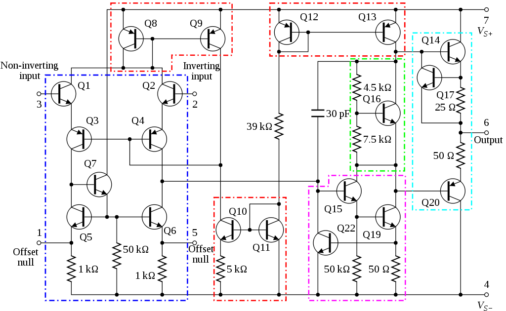
What you see below is the abstraction of the mesh of transistor shown earlier.

A Power Module

A Power Module

WHAT DOES OP-AMP DO FOR US?

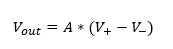
Well, they just simply produce output proportional to the difference in the voltage between the two input terminals. The proportionality constant is very high, order of 10^5, called the system gain, note Ed is in μV and o/p in V.

Mathematically,

A Power Module

The output characteristics for the device is as follows:

A Power Module

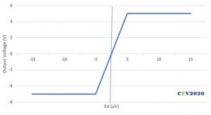
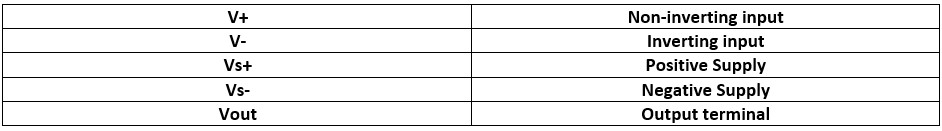
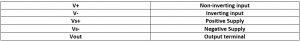
  • The magnitude of output voltage depends on the difference between in the input terminal voltage in active region and it saturates once output hits the supply voltage magnitude.
  • The polarity of output is same as the polarity of V+ wrt V-, thus V+ is called non-inverting terminal.

THE REAL OP-AMP

  • The variety of op-amps available are many LM324, LM339, LM258, etc. Most popular is IC 741. In our project we will use LM358, as it is single supply dual op-amp, so it will reduce complexity a bit.

A Power Module

A Power Module

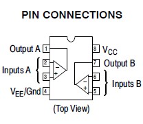
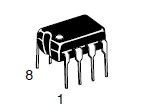
      Image courtesy: ON Semiconductors

THE RULES OF OPERATION

  1. The difference in input voltage is very small (typically in μV) so the two input terminals can be assumed to be virtually shorted, i.e. at same voltage.
  2. The input impedance is very high, so both the input currents are zero.
  3. The gain is infinity.

This is all one need to know about op-amp, using these three rules op-amps can be used very easily to get required gain.

Let’s check it out.

ROUTINE EXAMPLES

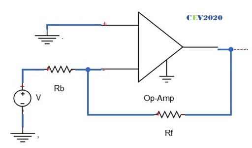
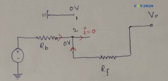
Inverting configuration:

A Power Module

Just calmly apply the rules one by one.

  1. Input terminals at same voltage, so voltage at 2 is voltage at 1, i.e. zero.
  2. No current through input terminals. Apply KCL at terminal 2:

A Power Module

A Power Module

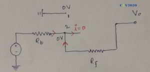
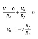
The characteristics become:

A Power Module

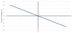
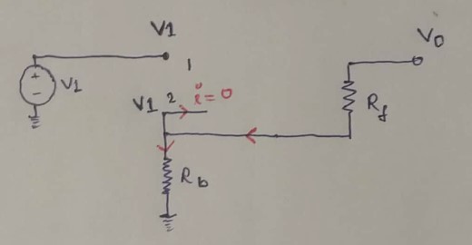
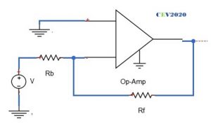
Non-inverting configuration:

A Power Module

Again, apply the same rules:

  1. Input terminals at same voltage, so voltage at 2 is voltage at 1, i.e. V1.
  2. No current through input terminals. Apply KCL at terminal 2:

A Power Module

A Power Module

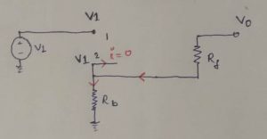
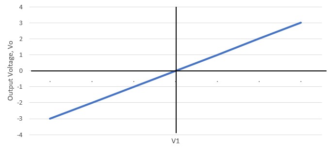
The output characteristics become:

A Power Module

So, are you now able to appreciate the beauty of these curves we just obtained??? We began with an op amp with typically infinite gain (10^5), showing very creepy dependence on the temperature and external factors and here is a calm stable op-amp with desired finite gain by just using simple passive resistances.

New gain of system become (Rf/Rb) and (1+ Rf/Rb), which remains fairly constant for a wide temp range.

HOW THE NEGATIVE FEEDBACK WORKS?

Though equations obtained by reasonable mathematical approximations shows us independence of overall gain, but intuition is still lacking….

So, how does the results we just obtained is manifested actually????

So, lets simply heat an op-amp working in a non-inverting configuration, and see what happens.

As heating begins the gain begins to rise, and so does the output voltage. Corresponding to it there will be rise in voltage at terminal 2. Which would result in lowering the difference between the two input terminals, and consequently the output drops. This drop in output leads to drop in voltage at terminal 2 which results in increased differential voltage resulting in increased output. These oscillations die out soon and result is stable output displaying temperature independent gain. This is in general how a negative feedback principle works.

IMPORTANT

Ensure that the power is never off when the inputs and output are connected in the op-amp.

……………………………………….

So, it’s time to get back from where we left, the need to boost up the sample voltage from 0-200 mV to 0-5 V range.

Pretty cakewalk now, isn’t???

You would say it’s a lockdown. Where should I get the op-amp?

Cool, there are whole lot of gadgets and sensors where you can find it.

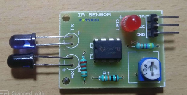
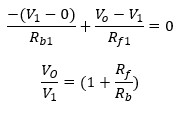
Say, for example, we extracted an op-amp from an IR sensor.

A Power Module

Due to unavailability of any solder iron, we just simply cut out the resistors, IR LEDs, POTs.

A Power Module
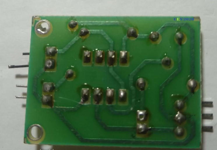
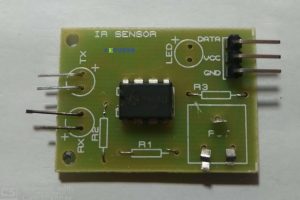
Using careful examination of the IC we traced out the whole IC circuit diagram.

A Power Module

And simply bought out the required terminals of op-amp by normal connectors.

A Power Module

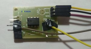
To boost the sample voltage from 0-200 mV to 0-5 V range, we need a gain of (5/200m = 25), since inverting is not desired hence using the non-inverting configuration.

A Power Modulewhere,

A Power ModuleRequired gain is 25.

A Power Module

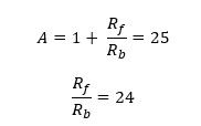
Let the resistances be: A Power Module

Finally, we used pair of resistors in combination to get the required ohms and made the op-amp circuit with a gain of 24.6 as follows:

DC CIRCUITS MEASUREMENTS

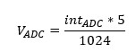
What we finally got is a 0-5 V scale that would end up giving us 0-1023 integer, we have to get all the way back to current, lets gooooo!!!!!🚀🚀🚀🚀🚀

Analog Voltage at the ADC:

A Power Module

Voltage input to the non-inverting amplifier:

A Power Module
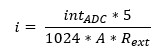
Current through the external resistance:

A Power ModuleThe overall conversion factor becomes:

A Power Module
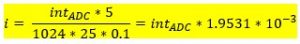
Putting our design values:

A Power Module

AC CIRCUITS MEASUREMENTS

Contribute

FREQUENCY AND POWER FACTOR MEASUREMENT

Underdev

DISPLAY LCD

All about LCD interfacing with the Arduino can be very easily understood by referring this short 1 min read at Arduino.cc.

https://www.arduino.cc/en/Tutorial/LiquidCrystalDisplay

We tried the same, followed every step very accurately but unfortunately, results didn’t show up except this blank screen.

A Power Module

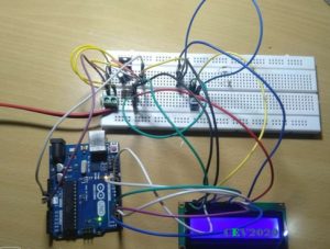
Help us to troubleshoot the problem by coming up with possible errors.

We build the icky circuit thrice from zero, and then checked and rechecked every connection, but failed.

MORAL:

  1. Life isn’t fair always, sometimes no matter how hard we try, no matter how dedicated our purpose is, we are destined to fail. We have realised this truth, and we hope to develop temperament to mindfully accept such failures in life.
  2. Connecting the circuit three times hadn’t yielded us the result, but surely planted in us the seed of perseverance to go through that nasty process. Surely, we raised our patience wall a little higher.

And it is these lessons and quality we wish to learn and develop by involving in these projects, not just simply putting things up.

THE FINAL CIRCUIT

Well do you think it’s done???

No, it’s not.

Since we are using same apparatus for the measurement of AC and DC. We hadn’t done anything to identify them. It can be done via program codes or by hardware.

By providing high or low manually on a digital pin we can indicate the microcontroller about it, say high for AC measurements and low for DC measurements.

THE FINAL CODES

#include <LiquidCrystal.h>
LiquidCrystal lcd(12, 11, 5, 4, 3, 2);

#define DCV_multiplier 0.499
#define DCC_multiplier 1.9531*10^-3

int read_voltage = A3;
int read_current = A4;
int select_pin = 7;
int voltage_adc_value = 0;
int current_adc_value = 0;
int voltage_peak_value = 0;
float dc_voltage= 0;
float ac_voltagerms= 0;
float dc_current = 0;
unsigned long sample_count = 0;

void setup()
{
  pinMode(A3, INPUT);
  pinMode (A4, INPUT);
  pinMode (7, INPUT);
  lcd.begin(16, 2);
  lcd.setCursor(0, 0);
  lcd.print("POWER MODULE");
  delay(3000);
  lcd.clear();
}

void loop()
{
  //Voltage Measurement//
  for(sample_count = 0; sample_count < 2000; sample_count ++)
  {
      voltage_adc_value = analogRead(read_voltage);
      if(voltage_peak_value < adc_value)
      voltage_peak_value = adc_value;
      else;
  }
      dc_voltage = voltage_peak_value * DCV_MULTIPLIER;
      ac_voltagerms = dc_voltage / 1.414;

  //Current measurement//
      current_adc_value = analogRead(read_current);
      dc_current = current_adc_value * DCC_MULTIPLIER;
    
  if ( select_pin==0 )
  {
      lcd.clear();
      lcd.setCursor(0, 0);     
      lcd.print("DC SYSTEM");
      lcd.setCursor(0, 1);
      lcd.print(dc_voltage);
      lcd.print("V");
      lcd.print (" ");
      lcd.print (dc_current);
      lcd.print ("A");
 else
      lcd.print("AC SYSTEM");
      lcd.setCursor(0, 1);
      lcd.print(ac_voltagerms);
      lcd.print("V");
      delay(500);
  }
}

A Power Module

LOCKDOWN SPECIAL

We could arrange a low resistance of required power handling capacity, so current measurements cannot be made. Moreover, the resistors required for the voltage multiplier are also not available with us. So, we used op-amp to get the required gain, slight code modifications and obtained the results using the serial monitor. Battery voltage is 12.25 V power module shows 12.33 V, 0.65% error.

A Power ModuleA Power Module

CONCLUSION

These power modules can be custom build for battery monitoring for systems like drones, etc. by removing AC measuring components and using small uC like Arduino NANO. They could be used for real-time monitoring of some load. They could be used to trigger some protective measures like triggering a relay, blowing a buzzer, etc. when any parameter beyond a limit.

The development or building of measurement systems is less about dwelling on rigorous electrical concepts rather more appropriately it could be categorized as a form of art, which requires small intuition of some very basic electrical phenomenon and rest is all about creativity to obtain the desired result by arranging the already available elementary elements.

If we could imagine force exerted on a wire carrying current in a magnetic field, if we can imagine emf induced in a changing magnetic field, if we can imagine magnetic field due to a coil carrying current, we are ready to go, about learning, understanding, modifying and building interesting measurement systems.

🍹🍹🍹

Keep reading, keep learning

AANTARAK DIVISION,

TEAM CEV!

References

  1. Special thanks to Prof Varsha Shah
  2. MIT OCW 6.002 Circuits and Electronics
  3. Mr Anand Aggarwal’s Fundamental of Analog and Digital Electronics
  4. Arduino.cc


THE DRAGON’S SCARE

Reading Time: 2 minutesThe corona pandemic has claimed many lives across the world. It’s other side effects include the widespread rampage on all sectors of economy of the world. It has caused the closure of many small industries, businesses and enterprises and it continues to haunt the future of  not only SMEs(Small and Medium Enterprises), MSMEs (Micro Small Medium Enterprises), Microfinance Institutions but also big companies.


In view of this, big Chinese banks, Private Equities and other multilateral instruments are investing heavily in such falling companies. These Chinese corporations work under the beneficial owner; the government of China. China’s recent increase in investment in HDFC bank has exceeded 1% which has poked the bear (RBI) into looking into this matter.


ATTRACTING INVESTORS IS GOOD, SO WHATS THE PROBLEM?

The problem is that by investing heavily they are buying shares of these companies at “THROWAWAY PRICES”. The impact of this, is that they will be majority stakeholders of these companies or aim to attempt buying them eventually (“HOSTILE TAKEOVER”). This will give them power to control these businesses and help them direct profit money to China.


China currently invests around $4 billion in Indian startups.18 out of 30 Indian unicorns (startups  having more than $1 billion market capitalization)  have Chinese funding.Big investors from China -Alibaba, Tencent , ByteDance have made huge investments in Paytm, Byju’s , OYO, Ola, Big Basket, Swiggy, Zomato. China dominates Indian markets in pharmaceutical APIs(Active Pharmaceutical Ingredients), mobile phone markets, automobiles and electronic and project imports.


THE DRAGON’S SCARE


HOW IS THE DRAGON’S MARKET INVASION BEING STOPPED?

The  Government of India and RBI (Reserve Bank of India) lost no time in rectifying it’s policies.The government has decided to screen Foreign Direct Investments (FDI) from countries sharing a land border with India or where the beneficial owner of an investment into India is situated in or is a citizen of any such country. The capital market regulator of India ,SEBI (Securities Exchange Board of India) is also digging deeper into  Foreign Portfolio Investors(FPI) composition from China, by seeking beneficiary details from jurisdictions like Mongolia, Bhutan, Nepal, Bangladesh , Afghanistan and Yemen.


SO WHAT’S NEXT?

These policy changes have put an end to such hostile takeovers yet other measures need to be taken in order to mitigate China’s sway over the market.


Squashing the Key Concepts related to Hyperledger Fabric

Reading Time: 6 minutes

Squashing the Key Concepts related to Hyperledger Fabric

Indeed you are at the right place 💖

I assume you already know about the key concepts of DLTs before you start reading this blog. If this is the case, let’s know more about Hyperledger Fabric.

What is Hyperledger Fabric and does it suits your use-case or application?

Hyperledger Fabric is a private and permissioned 🔐 DLT or a Blockchain to be precise, which comes under the umbrella of Linux Foundation.

As it is permissioned, one can not join or leave the network at any time. The members 👨 of a Hyperledger Fabric network enrol through a trusted Membership Service Provider (MSP), which we will discuss later.

The reason why it gains a mass adoption in Blockchain Marketplace is its modularity & flexibility. It allows to plug in different consensus algorithms, different database to save the data in ledger, and even allow to use different MSP to enrol users.

Hence, if you are looking for a Modular Permissioned-Blockchain Enterprise solution, Fabric can be the choice which you will definitely like.


Architectural Components of Fabric:

Like any permissioned blockchain network, Hyperledger Fabric has various actors & components like orders, peers, client applications, MSPs, CAs, etc. Let’s discuss them one by one.

1. Membership Service Provider:

Any of the actor 👨 in Fabric has an identity & according to the identity, the exact permissions and role of the actor are decided. So, from where do these identities come from and who decide the permissions? Yes, the MSP is the entity that defines rules, permissions and roles of different actors, whose identities have been issued by a valid CA(Certificate Authority).
The documentation says:

MSPs turn verifiable identities issued by CAs into the members of a blockchain network.

Summing up, an MSP abstracts away the protocols behind issuing certificates, validating certificates, and user authentication with all the cryptographic mechanisms, handled by CAs.

Note: Fabric comes with a built-in CA component, called Fabric-CA to allow you to create CA on the blockchain network. However, this component is pluggable and you still have to options to choose from other available CAs.

2. Peers
A peer is a node that hosts instances of the ledger and chaincode in the blockchain network. So, if an application or an admin wants to query the ledger or update the ledger then a connection with a peer is required.

A peer in the fabric network can hold more than one ledgers, which can be governed by one or more chaincodes.

https://hyperledger-fabric.readthedocs.io/en/release-2.1/peers/peers.html

https://hyperledger-fabric.readthedocs.io/en/release-2.1/peers/peers.html

A peer hosting multiple ledgers. Peers host one or more ledgers, and each ledger has zero or more chaincodes that apply to them. In this example, we can see that the peer P1 hosts ledgers L1 and L2. Ledger L1 is accessed using chaincode S1. Ledger L2 on the other hand can be accessed using chaincodes S1 and S2.

3. Orderer

An orderer node packages the transactions into a block 📦, which is then sent to peers, and after verification ✔️ appended to the ledger.

In a fabric network, there are various provisions for the configuration of orderer nodes. We can use a single orderer node (SOLO, deprecated from v2.0) or also a group of orderer nodes can be used to order the transaction and form a block, and this forms an ordering service.

As Fabric is a permissioned blockchain, and real message passing can take place between the nodes, so it doesn’t depend on probabilistic consensus algorithm for ordering of transactions like in the case of Bitcoin and Ethereum. So, all you have to do is to use the consensus algorithm provided by fabric, or you can plug in your own implementation.

4. Channel

Channel provides a mechanism for the peer to communicate & transact privately. Conceptually, each of the ledger in the network is associated with a channel and the peers which have joined the channel can view and transact on that ledger only.

Squashing the Key Concepts related to Hyperledger Fabric

In the above case, three channels C1, C2 &C3 exists, conceptually shown by black, blue, & orange rectangle. Peer P1 & P3 have joined blue channel(C2) and black channel(C1) and P2 & P4 have joined the orange channel(C3) and black channel(C1). So, the Blue ledger is maintained by P1 and P3, whereas Orange Ledger is maintained by P2 and P4, but black ledger is maintained by P1, P2, P3 and P4.

Here is another reference from Fabric’s Documentation:

Squashing the Key Concepts related to Hyperledger Fabric

P1 & P2 have joined channel C1 and thus can access the ledger L1. P2 & P3 have joined channel C2, thus can access ledger L2. The interesting part is peer P2 have joined both the channels, thus can access both the ledgers.

5. Ledger

Fabric’s Ledger 📒 is a distributed database with two components –

World State — the state of the ledger at a given point in time. So, world state stores the most recent value of assets in the form of key-value pairs.
Transaction Log — records all transactions which have resulted in the current value of the world state; it’s the update history for the world state.

A Ledger L comprises blockchain B and world state W, where blockchain B determines world state W. We can also say that world state W is derived from blockchain B.

A Simple Transaction:

Whenever a transaction is performed, it modifies the world state and the record of the transaction is made in the log of the ledger.

Squashing the Key Concepts related to Hyperledger Fabric

Note:

  • In Fabric, the database associated with the world state is pluggable and comes with two choices LevelDB & CouchDB.
  • Transaction log doesn’t need to be pluggable.

6.Smart Contract & Chaincode

Smart Contracts are the codes that contain the business logic in the fabric-network. It defines the business cycle of an asset in the world state. So the business logic inside the smart contracts governs all the transactions.

Here is a pseudo-code smart contract from the documentation:

Squashing the Key Concepts related to Hyperledger Fabric

Smart Contract ‘Car’ 🚗 defines the business logic to query, transfer and update the ownership of the car, agreed upon by Org1 & Org2

Smart Contracts are packaged into the Chaincode for deployment on the blockchain-network.

Think of smart contracts as governing transactions, whereas chaincode governs how smart contracts are packaged for deployment.

There are also some chaincodes which work on lower-level, to perform the necessary tasks in the blockchain-network, and they are called system chaincodes.

It is better to cover the chaincodes & transaction life-cycle in a different blog, later on 😺.

Squashing the Key Concepts related to Hyperledger Fabric

So that’s it. Thanks for reading.

Official Docs: https://hyperledger-fabric.readthedocs.io/en/release-2.1/

If you are facing difficulties in setting up Hyperledger Fabric, refer:

Hyperledger Fabric v2.1: Setting Things Up


Day20 – “Why?” & “What in?” Security & Blockchain?

Reading Time: 3 minutes

author: aman

Blog VIII - Part I - Day 20

Hey there, Sorry for time being away.

In the complete series the main focus was to get the undergrads of my college to a kind of "ROAD" that is not taken "usually". This was something out of the world of Competitive Coding and Machine Learning. Since the Internet is Changing, and Blockchains are the one who is the Lead Changer of this internet revolution. I guess, transformation would be the right word.

We have discussed about a lot of things, let's put them together.

In this micro-blog

  • Connecting the Dots
Connecting the Dots

So, we've talked about a lot of things in the series of the Blogs. However, I must say that I couldn't cover everything I knew in detail, but here I'll try to connect the dots for you.

Let me list the blogs with the topics they covered. (You are free to skip through the list, just come back if you want to grab a look at what has been already done.)

We talked about various sotware attacks, attacks on Blockchains, how terminologies(soundness, completeness) could mean so much, vulnerabilities, specs/invariants, bugs in few of the most trusted spaces. We also had 2 guest lectures in the series. Let me now end up with a complex case in case of Bitcoin.

The case leaves a possibility for an attacker to Partiotion the Bitcoin network into multiple parts, creating a possibility to fork bitcoin into 2 parallel chains. Let's see how it works:

BGP Highjacking attack on Bitcoin

The Bitcoin network is highly centralised, even after known to be a decentralised network. And even if the Blockchain is completely encrypted the routing of messages is still very much open. The routes are easily deductible to the adversaries.

See Here : https://bitnodes.io/

To explain it more, the complete Bitcoin network is spread to multiple ISPs (Internet Service Providers), which are again built up of multiple network clusters, called as Autonomous Systems(ASes). To communicate some messages between these ASes uses a protocol called the Border Gateway Protocol(BGP). This complete complete procedure is termed as Internet Routing.

~13 ASes host about 30% of the entire network, while 50 ASes host the 50% of the Bitcoin Network

Any attacker with accesss to the routing infra, can Highjack the BTC network. As a result of attacking mentality they can partition the BTC network in several parts. Probably bringing a major network towards their side.

Now they can add as many blocks in their side, and broadcast the chain in the network. By the general rule of Bitcoin network, "the longest chain is considered to be the final chain", the malicious one gets updated in the real etwork.

"hese attacks, commonly referred to as BGP hijacks, involve getting a router to falsely announce that it has a better route to some IP prefix."

"50% of Bitcoin mining power is hosted in only 39 prefixes (i.e., in 0.007% of all Internet prefixes). This allows an attacker to isolate ~50% of the mining power by hijacking only these 39 prefixes. Much larger BGP hijacks (involving orders of magnitude more IP prefixes) are routinely seen in the Internet today."


You see this is a big thing. The Internet Routing has a developing history of more than 35 years, and the BGPs are still considered to be stable. It is said that, Bitcoin has already gone through hundreds of BGP routing attacks, and the attacks are still not deductible.


So turning back and seeing the dots to be connected, we find,

  • a 100% secure system isn't possible
  • not a lot of people are aroung the security of these systems
  • the higher institutes are still hustling to create an environment of secure information exchange
  • developing techniques to check a system for its security is extremely difficult, and this is the place where actual computer science comes in
  • the attack surfaces are open in Hardware devices as well,
  • the Finance field is already being exploited for its vulnerabilities and application for the Blockchain tech

One thing to notice is that, even if the Blockchain tech fails, there will be a definite transformation in the internet we will be using tomorrow.

The security is everything. For a world running on Data, User's privacy, access to the systems comes in first.

So, that should be a lot of motivation I guess. I don't have any pre compiled list of the things, one can work on in the future, but BLOCKCHAIN + SECURITY, is surely the most citable area of work.

I'll try to cover more in details sometime. And yeap, I never read the Blogs twice, so pardon for the errors.

Shoot your questions and error reporting here aman0902pandey@gmail.com.

- Aman Pandey

amanpandey.codes

Hyperledger Fabric v2.1: Setting Things Up

Reading Time: 6 minutes

This article will take you to the easy steps for setting up Hyperledger Fabric v 2.1. It will be in reference to the Hyperledger Fabric Official Documentation, with short explanations at each & every step to save your time. I have seen, there are small-small things which people usually miss while setting up a fabric-network and face a lot of difficulties because of choosing the wrong version of dependencies, exporting wrong paths and many more things. So, my main motive to write this blog is to see you running the test-network, without missing anything.


* I will be using a Ubuntu 18.04 VM, on GCP for setting up the test-network.

Aye Aye Captain!! 🚢, let’s sail…

Installing the Pre-requisites & Getting the fabric binaries:

Just keep following the steps with me 😉:

  • Install curl, docker, docker-compose, nodejs & npm.
sudo apt install curl docker docker-compose nodejs npm

2. Install golang

Don’t install golang using apt, because ubuntu generally maintains an older version of golang 😕. Use official website of golang to download it, and follow me:

a)Use curl or wget to download the current binary for Go from the official download page:

wget https://dl.google.com/go/go1.14.2.linux-amd64.tar.gz

b)Extract the tarball

tar -xvf go1.14.2.linux-amd64.tar.gz

c)Adjust the permissions and move the go directory to /usr/local:

sudo chown -R root:root ./go
sudo mv go /usr/local

d)Adjust the Path Variables in .bashrc

export GOPATH=$HOME/go
export PATH=$PATH:/usr/local/go/bin:$GOPATH/bin

e) Load the file commands into the current shell instance

source ~/.bashrc

Note: Always check the minimum-version of any of the pre-requisites to avoid hustle.

3. Enable docker to run on

sudo systemctl enable docker

4. Add you, user, to the docker group

sudo usermod -a -G docker <username>

5. Install Fabric binaries

curl -sSL https://bit.ly/2ysbOFE | bash -s

6. Export path to your download location of fabric samples

export PATH=<path to download location>/bin:$PATH

You can see the following docker images pulled in your system now, by using

docker images

Hyperledger Fabric v2.1: Setting Things Up

Okay, after all this you are now in stage to test the first-network example provided by hyperledger fabric.

Hyperledger Fabric v2.1: Setting Things Up

Playing with the Fabric test-network bed:

To begin, change the current directory to the test-network folder and let’s move on.

Make sure there is no container related to Hyperledger Fabric is running before proceeding. Use these commands to stop them:

./network.sh down

            or

docker rm $(docker ps -aq)

Architecture of test-network:

The test-network which comes with Fabric v2.1 contains 2 Organizations with 1 Peer each and an Orderer organization with 1 peer.

You can see the ccp-generate.sh for knowing configurations related to orgs.

Hyperledger Fabric v2.1: Setting Things Up

Also, configuration required to generate the crypto materials for peers and orders is present in yaml files in cryptogen folder.

Check out some snaps 📷 from crypto-config-org1.yaml file from the cryptogen folder:

Hyperledger Fabric v2.1: Setting Things Up

Hyperledger Fabric v2.1: Setting Things Up

You can see the Template Count set to 1. It corresponds to the fact that only one peer will be created for the org, and crypto material is generated for that only.

Let’s move to the demo in just three steps:

Step 1: Bringing up the test-network

./network.sh up

If everything completes smoothly, then you will be able to see the following three containers- two peers & one orderer.

Hyperledger Fabric v2.1: Setting Things Up

So what actually happened in the previous command, the answer lies in the network.sh.

Hyperledger Fabric v2.1: Setting Things Up

The command ./network.sh up itself calls two functions to create orgs and create consortium.

Hyperledger Fabric v2.1: Setting Things Up


You can see that cryptogen is using the config files residing in organisations folder.

Note: One good enhancement in the test-network in v2.1 is that it also has an option to create identities using fabric-ca. Earlier version created the identities and crypto materials using cryptogen tool. So now it’s on you to choose the fabric-ca or cryptogen to generate the cryptographic materials for orgs. And, as matter fact Fabric doesn’t care at all about from where does the identities/certificates came. It just use them form verification and signing.

Similarly, the code to create org2 and orderer using config files from organisation folder is also present in the same function.

On the very next step, the createConsortium function will create a genesis block in the orderer system channel.

Hyperledger Fabric v2.1: Setting Things Up

That’s all you have all the necessary containers up at this stage and we can move on the next step to create a channel for transactions between Org1 and Org2.

Step2: Creating a channel

The createChannel() function in network.sh will use createChannel.sh script residing in the scripts folder.

Take a look at the script and you will find, it performs the necessary tasks like updating the anchor peers, creating channel and making the peers to join the channel.

So let’s fire the function using:

./network.sh createChannel

Whoops, you are one step closer to test the network.

Okay, so the last step is to deploy the chaincode on the peers corresponding to the channel which you have just created.

Step3: Deploying the ChainCode

./network.sh deployCC

Check out the script deployCC.sh. It packages, install and instantiate the chaincode on peers.

We will discuss the chaincode structure in a separate blog. Hope I will write it soon 👯 .

Now you are free to interact with chaincodes. But…

Hyperledger Fabric v2.1: Setting Things Up

From Fabric v2.0, Docker daemon dependency has been eliminated. So, now you can directly use the peer CLI to interact with your network.

To interact first with the peer CLI make sure:

  • You have exported the path to fabric binaries, which I think we have already covered in Pre-requisites steps.
  • Export the path to config folder in fabric-samples.
export FABRIC_CFG_PATH=$HOME/fabric-samples/config/

After that you are ready to go, you just need to export environment variables for Org1, if you want to use that.

export CORE_PEER_TLS_ENABLED=true
export CORE_PEER_LOCALMSPID=”Org1MSP”
export CORE_PEER_TLS_ROOTCERT_FILE=${PWD}/organizations/peerOrganizations/org1.example.com/peers/peer0.org1.example.com/tls/ca.crt
export CORE_PEER_MSPCONFIGPATH=${PWD}/organizations/peerOrganizations/org1.example.com/users/Admin@org1.example.com/msp
export CORE_PEER_ADDRESS=localhost:7051

After that, you are ready to go to interact with the chaincode installed on the peer.

So, let’s try the query command:

peer chaincode query -C mychannel -n fabcar -c ‘{“Args”:[“queryAllCars”]}’

Similarly, you can invoke other methods of chaincode.

You can also use some other chaincode residing in the chaincode folder of fabric-samples by modifying the deployCC script, or even you can test your own chaincode on the test-network.

Celebrate, you are now aware of managing a Hyperledger Fabric simple network and taking the reference of this test-network, you can design your own network and feel like a Blockchain Architect.

Feel free to discuss some of the errors you may encounter while setting up the network, in the comments.

I’m leaving my bash.rc important exports in case you missed something:

export GOPATH=$HOME/go
export PATH=$PATH:/usr/local/go/bin:$GOPATH/bin
export PATH=$HOME/fabric-samples/bin:$PATH
export PATH=$PATH:$GOPATH/bin
export FABRIC_CFG_PATH=$HOME/fabric-samples/config/

Don’t forget to clap, if this blog saved your time 👏 👏 👏

Hyperledger Fabric v2.1: Setting Things Up

References:

HTML Canvas Games from Scratch #4

Reading Time: 6 minutes

HTML Canvas Games from Scratch #4

Hello devs!🎮
Let us continue with the game👾
Now we need to implement these functionalities to complete the game:

  • Collide bullets with aliens
  • Healthbar for the player
  • Respawning of aliens
  • Background
  • Score calculation and game over

Let’s do it! 🚀

Phase 4

So we will begin with the code we left last time.
If you don’t already have it, you can download it from : HERE
So we will follow the order of functionalities given above.

Bullet alien collision💥:

So the alien should die if the bullet touches the alien’s body. To do this we will implement a distance() function which will take the coordinates of the alien and the bullet in consideration and check if any collisions occur. We will be iterating through the array Aliens and the array Bullets to check for each pair of {alien , bullet} to check for a collision. Let’s code!

//Checking for bullet kill  
for(i=0;i<Bullets.length;i++)  
{  
for(j=0;j<maxAliens;j++)  
{  
if(Math.abs(Bullets[i].x - Aliens[j].x) <= 18 && Bullets[i].y <= Aliens[j].y && Bullets[i].y>=Aliens[j].y-20 && (player.y - Aliens[j].y) >= 38 )  
{  
kills++;  
Bullets[i].y = -10;  
var addAlien = new alien(Math.random()*(window.innerWidth-100)+60, Math.random()*(window.innerHeight/2-300),Math.floor(Math.random()*2));  
Aliens[j] = addAlien;  
}  
}  
}  

Now let us analyse this code.

We are traversing through both the arrays and checking for 4 conditions :

  • Absolute distance between bullet and alien in x axis is less than or equal to 18 (as the aliens are almost 36px in width).
  • The y coordinate of the bullet is less than the y coordinate of the alien.
  • The y coordinate of the bullet is greater than ( alien.y - 20 ).(as the aliens are almost 40px in height)
  • The y coordinate of the space shuttle (center) is at least 38px below the aliens center.(this ensures that the alien and space shuttle are not )

If these conditions are satisfied, we :

  • Update number of kills (variable kills++)
  • Send the bullet out of the screen (y = -10)
  • Add a new alien in place of the dead alien.

Source Code : Code Link
Location in repository : \Phase 4\BulletCollisions


Try and run this code yourself to see the output.

Healthbar❤️:

For this we define a new variable called healthBarHeight.
So out health bar height will depend on the health variable, which is initially valued 90. As the aliens touch the shuttle, or the aliens *pass beyond the screen *, the shuttle’s health is reduced.
Turning it into code :

//Drawing the health bar  
c.beginPath();  
if(health == 90){  
c.fillStyle = "green";  
healthbarHeight = 90*6;  
}  
else if(health == 60){  
c.fillStyle = "orange";  
healthbarHeight = 60*6;  
}  
else if(health == 30){  
c.fillStyle = "red";  
healthbarHeight = 30*6;  
}  
else{  
healthbarHeight = 0;  
}  
c.fillRect(20, 20, 20 , healthbarHeight );  
c.closePath();  
c.fill();  

Note : All this is written inside the draw() function.

Well we also need to handle the cases where the player loses health. Write this inside the draw() function :

for( j=0 ; j<Aliens.length ; j++)  
{  
if(Math.abs(Aliens[j].y - testShuttle.y) <= 60 && Math.abs(Aliens[j].x - testShuttle.x)<=18 || Aliens[j].y >= window.innerHeight -30){  
health-=30;  
var addAlien = new alien(Math.random()*(window.innerWidth-100)+60, Math.random()*(window.innerHeight/2-300),Math.floor(Math.random()*2));  
Aliens[j] = addAlien;  
}  
}  

Try to check what conditions are handled.


Note : As soon as any of the conditions are satisfied, we have also killed the alien. Try removing the last 2 lines inside the if statement and then run the code and see the outcome.

The healthbar would looks something like this :
https://github.com/jrathod9/Making-of-Space-X-/blob/master/Phase%204/Health/Healthbar.png

Source Code : Code Link
Location in repository : \Phase 4\Health


Note : We still need to add the “Game Over” condition. We will do that at the end.

Before moving forward, let us code to increase the difficulty with score.
I.e. as kills increase, so will the speed of the aliens and the number of aliens:

var level = 0; //Declare this at the top  
  
//Increase difficulty with kills  
//Add this inside "Checking for bullet kill" after Aliens[j] = addAlien;  
if(kills % 10 == 0){  
alienSpeed += 0.1;  
}  
if(kills % 20 == 0){  
level++;  
var levelupAlien = new alien(Math.random()*(window.innerWidth-100)+60, Math.random()*(window.innerHeight/2-300),Math.floor(Math.random()*2));  
Aliens.push(levelupAlien);  
maxAliens++;  
}  

At every 15 kills we add a new alien, and at every 10 kills we increase the speed.
Source Code : Code Link
Location in repository : \Phase 4\LevelUp

Background✴️:

The game is set in outer space, so whats missing?
Right! Stars✨!
Lets code this separately first:

var maxStars = 150; //Stars on the screen  
var starSpeed = 5;  
  
//Star object  
var star = function(x,y ,rad){  
this.x = x;  
this.y = y;  
this.rad = rad;  
}  
  
Stars = new Array(); //Array of stars  
  
//Filling the array  
for(a = 0; a<maxStars ; a++){  
var temp = new star(Math.random()*(window.innerWidth-20), Math.random()*(window.innerHeight-20),Math.random()*3 );  
Stars.push(temp);  
}  

Now we will be drawing these stars, but every time a star leaves the screen we will place it back on the top. Hence it will be like a single screen just repeating itself.
This is how most of the infinite runner games like temple run and subway surfers take up just a few MB of space.
So here goes the draw function :

function draw(){  
//Clear window  
c.clearRect(0,0,window.innerWidth, window.innerHeight);  
//Draw stars  
for(j = 0;j<maxStars ; j++){  
c.beginPath();  
c.fillStyle = 'rgba(255,255,255,0.7)';  
c.arc(Stars[j].x,Stars[j].y,Stars[j].rad , 0 , Math.PI * 2 , false);  
Stars[j].y += starSpeed;  
//This part send the star back to the top  
if(Stars[j].y >= window.innerHeight-20){  
Stars[j].y = 0;  
}  
  
c.closePath();  
c.fill();  
}  
requestAnimationFrame(draw);  
}  
draw();  

Result:
https://github.com/jrathod9/Making-of-Space-X-/blob/master/Phase%204/Background/background.gif

Source Code : Code Link
Location in repository : \Phase 4\Background

Now we need to add this to the game . The background will be drawn regardless of what’s going on in the game so let us straightaway merge the code in the game code, resulting in :

https://github.com/jrathod9/Making-of-Space-X-/blob/master/Phase%204/BackgroundMerged/GameWithBackground.gif

Source Code : Code Link
Location in repository : \Phase 4\BackgroundMerged

Its time to wrap it up by calculating the score and handling the game over condition.

Game 0ver🎌:

To calculate the score there may be different ways. It totally depends on you how do you want to calculate the score.
I personally feel it is best to check the Accuracy and Level Reached:

var alive = 1; //1 alive 0 dead  
..  
..  
function draw(){  
//Enter code to draw Stars  
..  
..  
if(alive)  
{  
//Rest of the game  
..  
..  
//Check if alien touches shuttle or crosses screen to reduce health  
..  
..  
if(health == 0) //Check if health is 0  
alive = 0;  
..  
..  
}  
else  
{  
//Score screen  
c.beginPath();  
c.fillStyle = 'rgba(255,255,255,0.5)';  
c.font = "30px Calibri";  
c.fillText("GAME OVER!" , (window.innerWidth-20)/2 - 55 , (window.innerHeight-20)/2 - 30);  
c.fillText("Kills : " + kills , (window.innerWidth-20)/2 - 15 , (window.innerHeight-20)/2 );  
c.fillText("Accuracy : " + (kills*100/totalBullets).toFixed(2), (window.innerWidth-20)/2 - 55 , (window.innerHeight-20)/2 + 30);  
}  
requestAnimationFrame();  
}  
draw();  
..  
..  

This is how the game over screen will look:

https://github.com/jrathod9/Making-of-Space-X-/blob/master/Phase%204/Final/GameOver.png

So we are now ready with the final game:
Source Code : FINAL GAME
Location in repository : \Phase 4\Final

I’ve added a flickering effect to the alien as it looks cool. 😉
Enjoy playing and share it with your friends too! You can now experiment with the code to add your own effects, functionalities, audio, video and much more.

Play This Game
Play Another Version

Well this is the end of the series. Hope you try and create more such games and visuals on canvas.

If you liked canvas check THIS out!
Do leave suggestion/comments if any.
Cheers!🍬


Written by : Jay Rathod💻
Links : Portfolio | Github | Codepen | Linkedin | Instagram

CEV - Handout