Before I start with the topic, I want to discuss a concerning evil, the plagarism. As a team CEV promises to be authentic with its contents. The blogs published here are written by truly dedicated and passionate writers, hence we want you to be sure of ideas and facts presented here, they are not just copied and pasted, but articulated with sincere and dedicated effort. In every blog, the writer has a special interest and had gained knowledge through devoted study and exploration, enjoy reading!
This blog is intended to answer many of your questions which usually cruise in your mind whenever you travel by train if you are curious about how actually things work and have a sense of wonder. Indian Railways is really a masterpiece of engineering. From the diesel power to electric supply, from signalling to various megastructure required, it involves bright minds of mechanical, electrical, civil, electronics and communication and computer engineers to make a safe journey. It is basically an ecosystem of engineers where everyone shares an equal importance and significance.
So following are the question which you will find satisfactory rather thrilling answers,
HOW DOES ELECTRIC TRACTION WORK?
WHY ELECTRIC APPLIANCES LIKE FANS AND TUBELIGHTS OPERATE AT 110 V?
WHAT ARE RATING OF MOTOR USED?
WHICH TYPE OF MOTORS ARE USED AND WHY?
HOW AND IN WHICH PHASE ELECTRICITY IS PROVIDED TO LOCOS? and many more……..
Starting with some of most fascinating facts about our Indian railways
1. It is fourth largest railway network in world by size, 49% routes electified with 25 KVA, runs more than 20,000 passengers trains and more than 9200 frieght trains daily.
2. IR transports 8.26 billion passengers daily which is 1.9 % of Indian population!
3. It is world’s eight largest employer, it had 1.308 million employees as of March 2017.
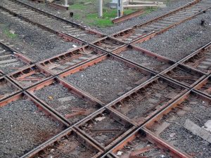
4. Diamond crossing in Nagpur is one of its kind, only used by IR. Trains there go east, west, north and south.
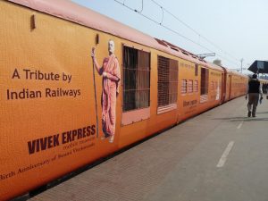
5. World’s largest in IR are: Vivek Express has the longest route in India, which covers 4,286 km in about 82 hours and 30 minutes, the train runs between Dibrugarh and Kanyakumari. IR also has longest platform of Gorakhpur.
6. Srirampur and belapur are two stations in Maharastra situated at the same point on track, but located on opposite sides of track.
7. The mascot for IR is Bholu, the guard elephant.
So, aren’t you amazed and feel proud be one of its traveller.
Coming to the topic, we are now going to discuss about electric traction in trains. What we use in electric cars is battery because power involved there is much smaller, if we talk about trains, it involves transporting over 1000 passengers at overhauling speed of around 100 Kmph.
In general one of aspect of engineering is that it involves “LARGE”, it comes with raised magnitude of everything, like SMALL HUT doesnt involves that much considerations but if you go for something like BURJ KHALIFA then you cant go random, operation of BULLOCK CART is simple but if its mass, its velocity, its power is increased we approach to a BULLET TRAIN, which is not at all plain sailing.
Lets first talk about power supply system to these massive machines.
The power starts its journey from some thermal power plant, hydroelectric power plant or nuclear power plant, it travels through the three phase national power grid and reaches the power sub-station beside the railway stations. The supply available locally can be at 400 KV, 132 KV, or 3.3 KV, irrespective of that, supply fed to the over-head wire is at 25 KV, single phase, by using required voltage transformation.
Below is basic circuit diagram of an externally powered electric traction system.
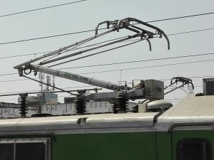
Like most of device, a train is also one port system. One terminal connected to the over-head wire through element called pantograph, another terminal connects to the track through the wheels, hence completing the circuit. The grounding of rail-tracks is very-very imporant, to maintain zero potential difference between track and ground. Sometimes return conductors are employed with boosters transformers instead of rail tracks for this purpose.
So we can break the whole power system into following components :
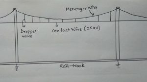
The overhead wire : You all know that any wire suspended between two poles will have a sag. These sags will cause discontinuous power and improper functioning. Clearly, we can not increase the no of poles to great number to check sag. Following technique is used:
First, the messengers wires are laid on poles and the contact wires are suspended through more no of droppers wire to minimise sag.
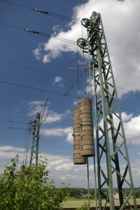
To help maintain proper tension in messenger wire due to seasonal changes we have an automatic tensioning device, many of you would have seen.
Then comes the pantograph: It is made of low friction, conducting graphite mounted on the roof of trains to collect power from overhead line. These are prone to great wear and tear, especially in very high-speed trains. They are replaceable. But, they also present a technical glitch i.e. wear and tear occur only at single contact point, and whole rod becomes inoperable, engineers came with a very fascinating solution.
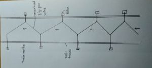
The over-head lines are arranged in zig-zag fashion so that the contact point on pantograph moves as trains moves on rail, hence undergo uniform erosion over the length, thus life expectancy of the pantograph is greatly increased by this simple arrangement of over head lines.
Once power recieved at 25 KV from pantograph, it is stepped down to a suitable level.
It’s a well-established fact that three-phase induction motors are superior to the single phase motor in every aspect, from the simplicity, self-starting, efficiency, power to weight ratio, starting and maximum torque and so on. On the other hand, it would also be very clear that we can not at all supply trains with three phase supply, it would make electrification of track greatly complicated.
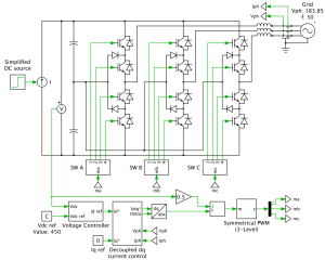
We supply with 25 KV single phase but run the train with three phase induction motor, thanks to the micro-electronics of today’s world. From the step-down transformer to the induction motor everything in between inside the massive engine is there to get a three-phase supply with easily controlled voltage and frequency (for speed control) to drive three-phase hungry motors.
IGBT circuit: This technology is used for conversion of single-phase voltage to a three-phase balanced voltage supply. It follows following steps: AC rectified to upf DC supply using GTO thyristors, filtering of DC, then inverted and given required phase shift to get 3 phase balanced supply using multiple insulated gate bipolar transistors (IGBTs). Details would be described in the next blog THE IGBT TECHNOLOGY: INDIAN RAILWAYS.
Some questions left are:
Q. Why AC motors not DC motors used in electric traction?
Ans : There is no doubt that DC motor have very easy speed control compared to induction motors, but they are being phased out because of many reasons : Simple and rigid construction of AC motors makes it resistant to great vibrations and shocks whereas DC’s components are subject failure, easy regenerative braking makes induction motor highly desirable in the industry, greater power to weight ratio, better power factor, low maintenance, etc all these facts prove that three phase induction motor is ideal for high-powered traction systems.
Q.WHAT ARE RATING OF MOTOR USED?
Ans: The rating of traction motor used in WAG-9 series in IR engines: 850 kW, 2180V, 1283/2484 rpm, 270/310A, 2100 kg.
By-Rahul(2nd year)
Keep reading, keep learning!!
TEAM CEV!

