New Home

Mindbend Indeaz -Some Problems & Basic & Best Solution

Reading Time: 6 minutes

Artificial Growth of algae & subsequent drain of nitrogen based chemicals.

  • While searching for technical solution, one has to keep in mind that technology should not induce other problems while solving one problem.
  • Also when we say water management it’s not controlling our limit of use but to artificially induce natural recycle process by studying nature. The best way to tackle waste is to match it with waste utilization. Manipulation of waste is like shifting it from one system to another without actually reducing the same.
  • Here I will be talking on a method that study natural water recycling method and adoption of the same instead of chemical processes which solve one problem and create another.

Eutrophication:-

  • Eutrophication can be human-caused or natural. Untreated sewage effluent and agricultural run-off carrying fertilizers are examples of human-caused eutrophication. However, it also occurs naturally in situations where nutrients accumulate (e.g. depositional environments), or where they flow into systems on an ephemeral basis. Eutrophication generally promotes excessive plant growth and decay, favoring simple algae and plankton over other more complicated plants, and causes a severe reduction in water quality. Phosphorus is a necessary nutrient for plants to live, and is the limiting factor for plant growth in many freshwater ecosystems. The addition of phosphorus increases algal growth, but not all phosphates actually feed algae. These algae assimilate the other necessary nutrients needed for plants and animals. When algae die they sink to the bottom where they are decomposed and the nutrients contained in organic matter are converted into inorganic form by bacteria. The decomposition process uses oxygen and deprives the deeper waters of oxygen which can kill fish and other organisms. Also the necessary nutrients are all at the bottom of the aquatic ecosystem and if they are not brought up closer to the surface, where there is more available light allowing for photosynthesis for aquatic plants, a serious strain is placed on algae populations. Enhanced growth of aquatic vegetation or phytoplankton and algal blooms disrupts normal functioning of the ecosystem, causing a variety of problems such as a lack of oxygen needed for fish and shellfish to survive. The water becomes cloudy, typically colored a shade of green, yellow, brown, or red.
  • Naturally Algal blooms occur when excess of plant nutrient (Nitrates & Phosphates) is available in the water-A natural cleansing process.
  • These blooms have been found to destroy fishes in fresh water because of the low oxygen level initiated by planktons feeding on algae after death at the lower water level.
  • It has been found that the root cause of imbalance in water is excess of nitrates & phosphates. So the target should be root cause.
  • Thus we could encourage algal growth for nitrate reduction outside the fresh water body & thereby decrease the nitrate & phosphate level and also increase food for planktons /phosphorous fixating bacterias/nitrogen fixating bacterias-which are then eaten by marine life-A natural phenomenon initiated artificially.
  • The excess of algae may be used as a bio-diesel or may be fed by phytoplankton to zooplanktons to small fishes to large fishes & the eco-logic continues.
  • Well traditionally ion exchange methods used in industries are used for nitrate reduction however nitrates do not go away from system they are just removed from water source & they appear in other system.eg:-

In ion-exchange resins the nitrate ion is removed from water source by exchanging with chloride ions. After the exchange the nitrates present in the resin bed are exchanged with HCL to regenerate resin producing HNO3 .thus we see that still overall system –the eco-system has nitrates still left & will somehow or other reappear. Also the chlorides that we exchanged are also as dangerous as nitrates if present in large quantity. So any chemical process is a curtain to existing problem it no longer solves problem as a whole. A bio-chemical process is therefore best by observing nature.

  • Also biological dentrification is used in which nitrates are converted to Nitrogen gas.
  • The process is similar to denitrification done by anaerobic bacterias but those require organic food in plenty to convert nitrates ultimately each natural process comes down to bacteria and microbes level as they are natural scavengers but those attract pests and rodents bad odor etc.

Disadvantage:-

  • The time algal growth requires, the time planktons & other organism requires to complete a food-web is high .hence this system may be only used in areas where there is no continuous addition of nitrates-small industries letting off waste in 5 days, a farming site where agricultural run-off carries phosphates & nitrates during rainy season, a waste water treatment plant having large base for each pond for cultivation.

Use of reflectors as flyers controlled by the control station to reflect the amount of power in a cellular structure:-

  • In a cellular structure the transmitting & receiver (duplex antenna) is one that radiates micro-waves for mobile communication. Generally in urban areas where concentration of mobile phones is very high the towers are placed on residential towers or offices or shops etc.
  • There is a growing debate on whether the electromagnetic exposure can cause tumors or cancer. Although few researchers have shown the opposite but practically over exposure to micro-waves can definitely lead to a disorder because these waves tend to heat the body temperature when they pass through our body. The tissues break in to cells creating disorder in the body due to high temperature.
  • Even though limits of radiation are standardized by government ,continuous exposure is dangerous for all of us. people living near towers face high dangers of exposure while people far away likely do not .since power density of the antenna is high near the antenna & starts reducing as the distance increases.
  • So we can direct a high powered beam of radiations towards a secondary tower flying in the sky over a cellular structure at heights calculated for power required & that can be used as a transmitter receiver to be communicated with the base station.
  • This will always ensure uniform power spread & the affect of heat effect of micro-waves would be reduced.
  • This will ensure constant power density on surface of earth (exceptions hills, mountains etc.) to be used for purpose of communication rather than concentrated power density.


Disadvantages:-

  1. Mobile base station makers will have to share extra costs for making new equipment controllable from control tower as well.
  2. Finding out space in the sky for installing each such station over which we can place the flying station which will not be interfered by birds, airplanes, ionosphere reflection, etc.

Possibility/Feasibility:-

A free wireless internet service for developing economies called “Project Loon” was announced by Google & initially was surveyed in New-Zealand by a farmer for wireless internet by sending balloons carrying transponders receptors & efficient mechanism for looming around a particular region just like a geo-synchronous satellite. This will also be in India, South-Africa.

An ICT model for empowering rural population:-

Our government spends 60000 crore in Nrega-a scheme which is aimed at providing opportunities for employment in 100 days. A worker from rural area is made to toil for breaking stones & he gets his income from that. With bundles of corruption, this scheme neither utilizes individual potential of a farmer, a child, a painter, a porter goldsmith etc. to meet their expenses rural public do .Instead of this each village can have a “centre of internet” where everything that an urban Indian gets rural India also has.


  • Healthcare:

Supply of generic medicines as when needed, supply essential supplements for maternal ,child health through a WLAN connections each in one village, asking possible diagnostic questions to doctors who are unwilling to go to rural side, people will tell their day to day activities & doctors would suggest diseases that can occur or a database of diseases in different languages.

  • Entrepreneurship:

Popularity of village & direct details of those involved in sale of those materials online.

  • Current trends of market:

Current Wheat, Rice, Moong, etc. to give farmers a fare share of their products

Giving their new inventions on web may be integrated with National Innovation Foundation (NIF).

  • Education.


Robotic Arm Replicating Human Hand Movement

Reading Time: 6 minutes

 Topics

  1. Anatomy of Human Hand
  2. Present Data Glove Technologies
  3. Glove Accessories
  4. Applications
  5. My Project


1      Anatomy of Human Hand

anatomy_1

anatomy_2

Human hand has 23 degrees of freedom:

 4 in each finger,

3 for extension and flexion and

one for abduction and adduction;

thumb is more complicated and has 4 DOF;

leaving 3 DOF for the rotation of the wrist

2      Present Data Glove Technologies


  • Pinch Glove

    Pinch-Glove
    Image Courtesy: http://www.mechdyne.com/

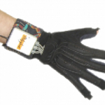
The first prototype, originally called the Chord Glove, was developed by Mapes at the University of Central Florida.Commercialized by Fakespace Laboratories (Mountain View, CA), it uses electrical contacts at the fingertips, on the back of fingers, or in the palm. When two or more electrical contacts meet, a conductive path is completed and a posture can be made. The PinchGlove interface detects whether a posture has been made and keeps a record of the posture duration. Postures can be programmed, and no additional posture recognition techniques are required. This makes the PinchGlove excellent for posture recognition with over 1000 postures theoretically possible.It uses polling algo. Asalient feature of this glove is that it does not require calibration. [1]

  • Didgi Glove  

    didgiglove
    Image Courtesy [1]

Commercialized by Didjiglove Pty, Ltd., the Didjiglove uses ten capacitive bend sensors to record finger flexion (fingers MCP and PIP, and thumb TCMP and MP). The sensors consist of two layers of conductive polymer separated by a dieletric. Each layer is comb-shaped; a change in the amount of sensor bending results in a change in the overlapping electrode surface, and ultimately in a change in capacitance. The Didjiglove requires calibration: to calibrate the glove, the user makes hand shapes and records these by pressing. It has small glove latency  (10ms)  It is designed for computer animation, and specifically to function as an advanced programming interface for toolkits such as 3-D Studio Max and Maya for which software drivers are provided. [1]

  • Cyber Glove

    Image Courtesy: http://www.vrealities.com/
    Image Courtesy: http://www.vrealities.com/
  • Cyber Force Image Courtesy: http://www.prweb.com/
    Cyber Force Image Courtesy: http://www.prweb.com/

 CyberGlove, created by Virtual Technologies, Inc. in 1990. Virtual Technologies was acquired by Immersion Corporation in September 2000. In 2009, the CyberGlove line of products was divested by Immersion Corporation and a new company, CyberGlove Systems LLC, took over development, manufacturing and sales of the CyberGlove.[2]

Image Courtesy: http://home.12move.nl/

It comes equipped with 18 or 22 piezo-resistive sensors. The 18-sensor model features two bend sensors on each finger (MCP and PIP joints), and four abduction/adduction sensors ,plus sensors measuring thumb crossover, palm arch, wrist flexion, and wrist abduction/adduction. The 22-sensor model features four additional sensors for measuring DIP joints flexion. Calibration is needed to make glove measurements insensitive to differences in users’ hands, finger length, and thickness and convert sensor voltages to joint angles. It is performed with the Virtual Hand calibration software by having the user flex their hand a few times and editing the gain and offset parameter value for each sensor to best match the motion of the virtual hand to the physical hand. [1]

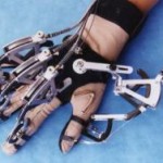
In addition to the CyberGlove, Immersion Corp also developed three other data glove products: the CyberTouch, which vibrates each individual finger of the glove when a finger touches an object in virtual reality; the CyberGrasp which actually simulates squeezing and touching of solid as well as spongy objects; and the CyberForce device which does all of the above and also measures the precise motion of the user’s entire arm.

  • Human Glove

Patented in 1997, it is commercialized by Humanware Srl (Pisa, Italy). It is equipped with 20 Halleffect sensors that measure flexion/extension of the four fingers MCP, PIP, and DIP joints and flexion/extension of the thumb TMCP, metacarpal phalangeal (MP), and interphalangeal (IP) joints, aswell as fingers and thumb abduction/adduction; two additional sensors measure wrist flexion and abduction/adduction.Glove calibration is similar to that of the CyberGlove and is performed through a software package called Graphical Virtual Hand, which displays an animated hand that mirrors movements of the user’s hand.

The Humanglove is a sensorized elastic fabric glove designed and commercialized by Humanware. The Humanglove is equipped with 20 Hall effect sensors. Each sensor measures data related to a DOF of the hand. The nominal sensor characteristics are resolution, 0.4° over a range up to 90°; linearity, about 1 percent full-scale output; and accuracy, about 1°. However, no information about the sensors is available concerning their performance when they are mounted on the elastic fabric glove.[1]

  • 5DT Data Glove 

Uses optical-fiber flexor sensors 1 sensor per finger to measure overall flexion of the

Image Courtesy: http://www.metamotion.com/

four fingers (average of MCP and PIP joint flexion) and thumb (average of MP and IP joint flexion)& 1 tilt sensor to measure tilt of wrist. Gesture library uses binary open/close configurations for the fingers, excluding the thumb, so that 2^4 = 16 possible gestures can be generated.   (V) [1]

3      Glove Accessories

A complete description of hand movement requires knowledge of

1. Hand configuration (amount of joint bending or joint relative positions)  – Sensor Glove

2. Hand position in space (location and orientation of the hand, for a total of 6 DoFs—3 for translations and 3 for rotations) – 3 D Trackers

Key performance parameters  of sensor– accuracy in dergrees , jitter, drift and Latency

Sensor are broadly classified into

  • Magnetic
  • Ultrasonic
  • Optical
  • Inertial
Tracker

Principal

Advantage

Disadvantage

Magnetic-Hall-effect eg RFID
Magnetic field producedby a stationary transmitter to determine the positionof moving receiver element lowcost, reasonable accuracy, and no requirement of directline of sight transmitter–receiver sensitivity to magnetic fields and ferromagnetic materials.
Ultrasonic
Ultrasonic signalproduced by a stationary transmitter to determine the positionof a moving receiver No metallic interference Suffer from echoes from hard surfacesRequire direct line of sight Update rate is approximately 50 datasets/s, less than half that of magnetic trackers
Optical
Uses optical sensing to determine the real-time position/orientation of an object Insensitive to metallic interference line of sightSensitivity to reflection of light from surfaces in theenvironment.
InertialEg Accelerometer
measures the rate of change of an object’s orientation or therate of change of an object’s translation velocity Unlimited rangeNo line-of-sight constraintsLow sensor noise Sensitive to drift and bias of thesensors


4      Applications

  • 3D Modelling
  • Virtual Training
  • Control a robot
  • Tech a robot in natural way
  • Video Games
  • Communication System for Deaf
  • Motor rehabilitation, human motion analysis
  • Wearable Computers
  • (V)

5      My Project

Till now I completed the survey of kinds of Data Glove and the kind of technology they use. I have also created my virtual reality model. Future steps I will undertake

  1. Decide Sensor’s which are most appropriate for my application
  2. Intergate sensors with hardware to process the data- NI Hardware  (V)
  3. Virtual Hand Designing in Autodesk Inventor(Completed)
  4. Integrating VR Hand  to sensory data – NI Labview

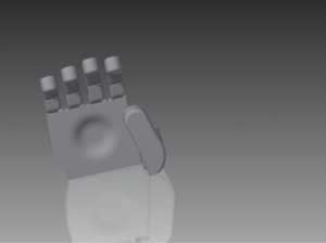
Pics of hand I designed in Autodesk Inventor


 myproject_5  myproject_2  myproject_1
 myproject_7  myproject_4  myproject_6
 myproject_7  myproject_9  myproject_3

So keep following this post for viewing the future work in this project!!!!!

#References

[1] Dipietro, L.; Sabatini, A.M.; Dario, P., “A Survey of Glove-Based Systems and Their Applications,” Systems, Man, and Cybernetics, Part C: Applications and Reviews, IEEE Transactions on , vol.38, no.4, pp.461,482, July 2008

[2] http://en.wikipedia.org/wiki/Wired_glove 

Applications & Basics of Bucky Paper

Reading Time: 5 minutes

Buck paper is an arrangement of carbon nanotubes in some desired fashion and orientation or we can say buckypaper is a macroscopic aggregate of carbon nanotubes (CNT’s).

The specific properties of bucky paper depends upon arrangement of CNTs . These properties include :

1)EMI ( electro- magnetic interference) Shielding.

2)Strength .

3)Electroconductivity.

4)Thermal stability.

By adding the resin and the hardener to the buckypaper and then curing it in a specific temperature and pressure, the buckypaper composite will be produced.

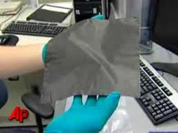
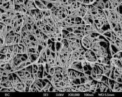
download-4download-5

Fig 1.                                                                              Fig 2

Fig1 shows picture of bucky paper composite.

Fig 2 shows SEM image of bucky paper.

Now before going in detail about bucky let us talk about its building block –CNT . We will learn what it is , its types , its preparation methods and properties.

Carbon Nanotube

Carbon is having 3 forms of allotropes: graphite, diamond and fullerene, and if we talk about graphene it has two dimensional hexagonal sheets one above the other.

Picture2Picture1Picture3

So if we roll  that two dimensional sheet we get CNT is a tubular form  with diameter as small as 1nm and length in few nm to microns.Picture4

The way that graphene is rolled up drastically change physical properties and we get different types of nanotubes.

We can define the nano tube in terms of the equation : Ch = n â1 + m â2,

Ɵ is Chiral Angle with respect to the zigzag axis and a1, a2 are chiral vectors.

The coefficients n, m define what kind of nanotube it is. For e.gPicture5

n= m armchair nanotube

m=0  zig-zag nanotube

n ≠ m chiral nanotube

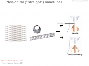
and under some conditions such as n-m =3r where r= 0,1,2..we get metallic nanotubes otherwise semiconducting nanotubes.


Picture61So we can say that- The values of n and m determine the chirality, or “twist” of the nanotube. The chirality in turn affects the conductance of the nanotube, it’s density, it’s lattice structure, and other properties. A SWNT is considered metallic if the value n – m is divisible by three. Otherwise, the nanotube is semiconducting. Consequently, when tubes are formed with random values of n and m, we would expect that two-thirds of nanotubes would be semi-conducting, while the other third would be metallic.

Types of carbon nanotubes: 

A)Single walled carbon nanotube                 B) Multi walled carbon nanotube


MWCNTS are concentric nanotubes.


Preparation methods:

As CNT is a thin two dimensional graphene sheet we will first learn how this grapheme layer is prepared. The simplest method to produce  graphene layer is chemical method.

Procedure:

1)Take graphite powder cooked it in acid (cons H2SO4) with an oxidizing agent (cons  HNO3), thus will give graphite oxide.

2) Graphite oxide will then reduced to give graphene.

3) now this graphene is in solution form , put this solution on any substrate we get graphene layer.

Fig3 below shows schematic procedure of chemical method.

Picture9

Second method most important method is Arc Discharge method.

images-1

This is the most common and perhaps easiest way to produce carbon nanotubes as it is rather simple to undertake. In this method two carbon rods placed end to end, separated by approximately 1mm, in an enclosure that is usually filled with inert gas (helium, argon) at low pressure (between 50 and 700 mbar) as shown in Figure 4. A direct current of 50 to 100 A driven by approximately 20 V creates a high temperature (~4000K) discharge between the two electrodes. The discharge vaporizes one of the carbon rods (anode) and forms a small rod shaped deposit on the other rod (cathode).

Third method is Chemical Vapour Deposition (CVD):

In short we can say that here we have a chamber in which substrate + catalyst is present and gas(carbon source) comes in and there will be:

Steps:

  • Adsorption
  • Dissociation of hydrocarbon.
  • Dissolution and saturation  of C atoms in metal .
  • Precipitation of Carbon.
  • Picture2

Properties of CNT:

  • Mechanical : Young’s modulus of the single walled carbon nanotubes (SWCNTs) can be as high as 2.8-3.6 TPa and 1.7-2.4 TPa for multiwalled carbon nanotubes (MWCNTs) which is approximately 10 times higher than steel, the strongest metallic alloy known.

Application:  the high stiffness and strength combined with low density implies that nanotubes could serve as ideal reinforcement in composite materials and provide them great potential in applications such as aerospace and other military applications.

  • Electrical: They can be can be metallic or semiconducting depending on their structure and their band gap .  Theoretically, metallic nanotubes having electrical conductivity of 105 to 106 S/m can carry an electric current density of 4 × 10⁹ A/cm2 which is more than 1000 times greater than copper metal .

Application:  So the high electrical conductivity of CNTs makes them an excellent additive to impart electrical conductivity in otherwise insulating polymers. Used in fuel cell technology.

  • Thermal: SWCNT has a room-temperature thermal conductivity along its axis of about 3500 W m−1 K−1 and MWCNTs have a peak value of ~ 3000 W m−1 K−1 at 320 K; compare this to copper, a metal well-known for its good thermal conductivity, which transmits 385 W m−1 K

Application: thermal management applications, either as “heat pipes” or as an alternative to metallic addition to low thermal conductive materials,heat sinks that would allow computers and other electronic equipment to disperse heat more efficiently than is currently possible


Preparation of Bucky paper


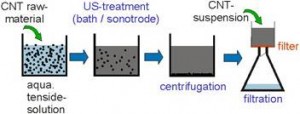
Now we have CNT’s ready with us in both forms SWCNT’s and MWCNT’s. We have to put these nanotubes in some desired fashion to form bucky paper,figure shown below clearly explains the procedure to do it:

Picture9Picture3


This is just the basics of bucky paper or CNT, if someone have to study in detail their is an excellent video  lecture from Prof C.N.R Rao, check it :

https://www.youtube.com/watch?v=8WwXAwBAtfg

Flow Boiling

Reading Time: 2 minutes

Boiling


Boiling is classified as pool boiling or flow boiling, depending on the presence of bulk fluid motion.


Pool Boiling and Flow Boiling

  • Boiling is called pool boiling in the absence of bulk fluid flow and flow boiling (or forced convection boiling) in the presence of it. In flow boiling, the fluid is forced to move in a heated pipe or over a surface by external means such as a pump or from height. Therefore, flow boiling is always accompanied by other convection effects.


Sub-cooled Boiling and Saturated Boiling

—        Boiling is said to be sub cooled (or local) when the temperature of the main body of the liquid is below the saturation temperature Tsat (i.e., the bulk of the liquid is sub cooled) and saturated (or bulk) when the temperature of the liquid is equal to Tsat (i.e., the bulk of the liquid is satu

Void fraction in a Gas-Liquid Flow


—        The fraction of the channel volume that is occupied by the gas phase.

—        The fraction of the channel cross-sectional area that is occupied by the gas phase.

—        Quality Profile :-  Vapour Quality is the percentage of mass in a saturated mixture that is vapour i.e. saturated vapour has a “quality” of 100%, and saturated liquid has a “quality” of 0%.

APPLICATIONS


—  This type of boiling take place in Nuclear reactors and Aerospace Engines.

—  Flow boiling is also used in the cooling of Electronic Circuit Boards using Micro channels.

—  All the refrigeration cycles are based on flow boiling.

—  Cooling systems in various industries comprise of Flow boiling.


Modern Marvel-Touch Screen

Reading Time: 9 minutes

Topics being covered :-


1.Introduction

2.Types of touchscreens

3.Resistive touch

4.Capacitive touch

5.Acoustic touch

6.Infrared technology

7.Comparison between various touchscreens


Introduction

Do you know what a touch screens is?

It is a human machine interface (HMI). HMI, as its name indicates, is an interface or device that allows communication between machine and its user.

A touch screen is also this type of HMI that uses images for communications between a user and electronic device. Unlike mouse and keyboard, touch screen allows a user to interact with electronic device by directly touching images displayed on the screen.

Touch screen itself is just a transparent switch that detects touched locations. How the device reacts to your touches is controlled by software. Various input devices can be made with combination use of touch screen, display and software.


Advantages

1. Switch and buttons are not physically required. Device makers can make and modify various input interfaces creatively by software.

2.With multi-touch function, various operations/inputs (eg: zoom-in/zoom-out, rotation) are possible.

3.Because a user operates an electronic device by directly touching the images on the display he is seeing, the operation will be intuitive, thus anyone can operate it from first use.

4.The whole unit is space-saving because display and input space are integrated. There is a lot of flexibility in design.

5.Unlike keyboard or physical switch, there will be no dirt, dust, and moisture getting into the spaces between buttons. Thus, it is easy for maintenance.


Disadvantages

1.Since a display is directly touched, the display may get dirty, then become less-visible. A direct touch may also cause scratches on the screen that may cause malfunction in some cases.

2.Unlike push-button and mouse, users will not feel “click” when a user input a touch screen, thus operation may become clumsy sometimes. However, there are certain touch screens that provide “click feeling” when touched.


Resistive touch


4 Wire Touchscreen

They are all constructed similarly in layers-a back layer such as glass with a uniform resistive coating plus a polyester coversheet,

with the layers separated by tiny insulating dots. When the screen is touched, it pushes the conductive coating on the coversheet against the coating on the glass, making electrical contact. (fig 2)

Analog 4-wire resistive is the most basic sensing method of resistive technology.

Top and bottom transparent conductive sheets that have uniform resistance value, are facing each other with a gap.

When the top sheet is touched, the touched point of the top sheet yields, and contact the bottom sheet.

The contacted point is conducted, and its location is sensed.

fig1

fig1

fig2

fig2


The sensing process (refer fig 1 for understanding)


1. Voltage is imposed between the electrode X1 and X2 on the top sheet. Then, there will be formed on the top sheet an equipotential distribution that is parallel to the X1 and X2.

2.Assuming that the electrode X1 is 0V (Ground), then impose 5V to the electrode X2. If the central point between the right and left electrodes is touched, 2.5V would be measured by the bottom sheet. If a    point 1/5 away from X1 (4/5 away from X2) is touched, 1V would be measured by the bottom sheet. The X coordinate point is detected in this way.

3. After detecting the coordinate point in X direction, Voltage is imposed between the electrode Y1 and Y2 on the bottom sheet. The point between Y1 and Y2 (Y coordinate) would be measured by the top sheet, just in the same manner as X coordinate in the step 1-2.

4.As the set of step 1 ? 3 is repeated, the X and Y coordinate points of touched locations keeps being detected.


5-Wire TouchScreen

In analog 4-wire resistive technology, one sheet has equipotential distribution in X direction, and the other sheet has equipotential distribution in Y direction.

The two sheets measure each others’ voltages. In analog 5-wire resistive technology on the other hand, one sheet (bottom sheet) has equipotential distribution in both X and Y directions. Voltage of the bottom sheet is measured by the top sheet.


The sensing process (Refer fig3 for understanding)


1. 5V is imposed on the electrodes A and C. The other side (electrode B and D) will be 0V (Ground). In this way, there will be formed an equipotential distribution parallel to AC and BD.

2.   Voltage of a touched point will be measured by the top sheet. If the central point between AC and BD electrodes is touched, 2.5V would be measured by the top sheet. If a point 1/5 away from AC (4/5 away from BD) is touched, 1V would be measured by the top sheet. Touched coordinate point in X direction will be measured in this way.

3.    After detecting the coordinate point in X direction, 5V is imposed on the electrodes A/B. Then, C/D will be 0V (Ground). The point between AB and CD (Y direction) would be measured by the top sheet, in the same manner as X direction.

4.  As the set of step 1 ? 3 is repeated, the touched points in X and Y direction keeps being detected.

fig 3

fig3

An analog 5-wire resistive sensor was regarded as more durable than analog 4-wire resistive sensor.Since,there is no equipotential

distribution formed on the top sheet in analog 5-wire resistive.

So, the top sheet did not need to be good at resistance uniformity and environmental durability in this sensing method.


8 Wire touchscreen


The structure and sensing method of 8-wire resistive technology is same as 4-wire resistive technology.

Two transparent conductive sheets are facing. One sheet has electrodes on right and left sides, and the other sheet has electrodes on top and bottom sides.

Voltage is imposed on the sheet with electrodes on right and left sides, then a touched point in X direction is detected as the voltage is measured by the other sheet.

Then, voltage is imposed on the sheet with electrodes on top and bottom sides, then a touched point in Y direction is detected as the voltage is measured by the other sheet.


fig 4

fig4

You would be thinking it same as 4 wire touchscreen??

Yes,you are right but there are additional wirings connected to each electrode in analog 8-wire resistive technology. Each electrode is added with one more wiring. These added wirings work as supplemental electrodes and measure voltage on each electrodes, then feedback the information to the controller.

Analog 4-wire resistive technology required calibration not only at the beginning but regularly because touch detecting points are gradually going off the alignment due to change of resistance value on wiring and/or connector parts with the passage of time. In analog 8-wire resistive technology, supplemental electrodes measure the voltage on each electrode automatically, and feedback the measured values to the controller. The voltage detected at touching is transformed into locational information in the relative ratio with the feedback voltage. In this way, the effects of voltage change at electrodes can be cancelled, thus recalibration would not be required.


Capacitive touch


There are two types in capacitive technology that are surface capacitive and projected capacitive.

Surface capacitive is employed for applications such as ATM and factory automation, but demand is limited.

As projected capacitive was developed and started to be employed for smartphone, the number of capacitive touch screen has been increasing dramatically.

Surface Touchscreen

Transparent conductive coating is on the base glass sheet, and glass protective coating is placed over it. Electrodes are placed on the four corners.

fig 5

fig5

Sensing Method

The same phase voltage is imposed to the electrodes on the four corners, then a uniform electric field will be forming over the panel. When a finger touches on the panel, electrical current will flow from the four corners through the finger. Ratio of the electrical current flowing from the four corners will be measured to detect the touched point. The measured current value will be inversely proportional to the distance between the touched point and the four corners.

fig 6.

fig6

Projected Capacitive

There are various structures in projected capacitive technology. “One sheet piled-up structure” has X and Y electrodes piled on one sheet. “One sheet two-sided structure” has X and Y electrodes on its surface and backside of one sheet respectively. “Two-sheets-laminated structure” consists of two sheets facing each other with electrodes in between.

fig 7

fi7

In the two-sheets-laminated structure of projected capacitive, X electrodes are forming on one glass, and Y electrodes are forming on another glass. The two glass sheets are laminated in the way that two electrode sides are facing. The X and Y electrodes are intersecting in matrix.

Sensing Method

There are two types of sensing methods in projected capacitive technology. They are GRID type and wire sensing type. GRID type will be introduced here.


Human body is conductive since it contains a lot of water. When a finger comes close to the patterning of X and Y electrodes, a capacitance coupling will occur between the finger and the electrodes. The capacitance coupling makes the electrostatic capacitance between the X and Y electrodes change. The touch sensor detects touched points as it checks where on the electrode lines the electrostatic capacitance changed.

fig 8

fig8

Projected capacitive technology make use of conductivity of human body. Then, you can imagine that projected capacitive can detect only fingers just like surface capacitive.

Projected capacitive can detect gloved finger as well.

fig 9

fig9


Acoustic touch


Surface acoustic wave technology makes use of ultrasonic waves for detection. It is often abbreviated to SAW.

Let’s look at the structure of the touch screen first.

fig10

fig10

Take a look at the fig10.

Surface acoustic wave touch screen consists of one glass sheet with transmitting transducers, receiving transducers, and reflectors. Transmitting transducers generate ultrasonic waves that travel over the panel surface. The ultrasonic waves are reflected by the reflectors and received by the receiving transducers.

The ultrasonic waves traveling over the panel surface are surface acoustic waves.

Sensing Method

1.If contacted by a soft material, SAW will get absorbed by it. Surface acoustic wave technology makes use of this nature of SAW.SAWs are sent out from the transmitting transducers, and traveling along the edge of panel. The reflectors located on the edge of the panel change directions of the SAWs at the angle of 90 degrees, thus the SAWs travel over the panel. Once the SAWs reached the other side of the panel, their directions get changed again by the reflectors located on the other side, and travel toward the receiving transducers. Once the SAWs are received by the receiving transducers, they will be converted into electric signals.

2.If it is touched by a finger, the SAWs will be absorbed by it and do not reach to the receiving transducer. Then, the sensor detects where the SAWs were absorbed?

3.There are routes on which the SAWs travel from the transmitting transducers to the receiving transducers. Each route has its own distance. If one of the routes is touched by a finger, the pulse will be absorbed, and the SAW on the route will not be received by the receiving transducers. Thus, the sensor will recognize which route was touched, and locate the touched point.


Basics of Cells & Battries

Reading Time: 7 minutes

Cells or Batteries are broadly classified into two four broad categories:

  • Primary cell
  • Secondary cell
  • Reserve cell
  • Fuel cell


Let us start with basic definition of these cells:

Primary cell:

  1. primary cell or battery is one that cannot easily be recharged back.
  2. Generally these cells contain electrolyte in the form of solid powdered state and that’s why these are also known as DRY CELLS.
  3. Cells contain electrochemical reactions which are non –reversible.
  4. These are having very low self discharge rate known as charge retention factor. Factors affecting self-discharge extent include: anode and cathode preparation course, electrolyte nature and concentration, and battery storage temperature and time, among which battery self discharge greatly depends on temperature.
  5. Examples: Zn–MnO2 cell which is most commonly used battery. This type of battery is available in different sizes- AA, AAA, C, D etc.

We discuss later on what is the difference in between them in terms of electrochemistry.


Let us understand electrochemistry of Zn –MnO2 cell:

Picture1

Understanding electrochemistry of any battery always divides the cell into separate anode region, cathode region, electrolyte used and separator material which separate anode and cathode.

So, here we have Zn metal at anode which reacts with electrolyte ammonium chloride as follows:

Zn(s) + 2OH(aq) → ZnO(s) + H2O(l) + 2e [e° = 0.76 V]

Emf(Ox) = 0.76 – RT/2F ln([Zn0]/[OH-]^2)……nernst equation


At  cathode MnO2 is there which will reat with two e-‘s on cathode eletrode surface i.e.

2MnO2(s) + H2O(l) + 2e → Mn2O3(s) + 2OH(aq) [e° = +0.5 V]

Emf (Red) = 0.5 – RT/2F ln ([Mn2O3]/[MnO2^2])


Add both anodic and cathodic half cell reactions we get:


Zn +MnO2 –>ZnO2 + Mn2O3


Emf total = Emf (ox) + Emf (red)

= +1.56 –RT/2F ([Mn2O3][ZnO2]/[MnO2])

The above process is discharge of cell but if we consider discharge of a battery we have to reverse the above reactions but thermodynamically this process is infeasible, and that’s why we cannot charge primary cells.

Secondary cell:

  1. Electrochemical reaction occurring in reversible in nature ,therefore we can recharge them
  2. e.g. : lead–acidnickel cadmium (NiCd), nickel metal hydride (NiMH), lithium ion(Li-ion), and lithium ion polymer (Li-ion polymer).

Lead Acid Battery

Lead–acid batteries, invented in 1859 by French physicist Gaston Plante, are the oldest type of rechargeable batteries. This is most widely used commercial battery used in    automobiles and heavy electronic devices because of its high current rating.

Let’s understand the mechanism of lead acid batteries:

Negative plate reaction: Pb(s) + HSO−4(aq) → PbSO4(s) + H+(aq) + 2e-

Positive plate reaction: PbO2(s) + HSO−4(aq) + 3H+(aq) + 2-e → PbSO4(s) + 2H2O(l)

                                                                          Discharging–>

Overall reaction: Pb(s) + PbO2(s) + 2H2SO4(aq) → 2PbSO4(s) + 2H2O(l)

                                                                        <–charging

ggggggggggg

Applying Nernst equation at room temperature for this case we get 2v.

I.e. Per cell voltage is 2v.Therefore 6 cells are stacked together to form 12v battery having 13.9 amp-hours per kg.


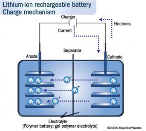
 Similarly we can think of Lithium ion battery, they are one of the most popular types of rechargeable battery for portable electronics, with one of the best energy densities, and only a slow loss of charge when not in use.

Picture2


Reactions:
Positive electrodes: LiCoO2- =   Li1-x CoO2 + xLi + xe-
Negative electrodes:  C+xLi+xe-  =   CLix
Discharging–>

Battery as whole:    LiCoO2 + C  =   Li1-x CoO2+CLix
<– charging

  • During discharge, lithium ions Li+ carry the current from the negative to the positive electrode, through the non-aqueous electrolyte and separator diaphragm.
  •  Picture4Picture5
  • Pure lithium is very reactive. It reacts vigorously with water to form lithium hydroxide and hydrogen gas. Thus, a non-aqueous electrolyte is typically used, and a sealed container rigidly excludes water from the battery pack.


Now next is Reserve batteries :

  •  These batteries are working as normal batteries but cell is inactive (dead) until and unless cell certain condition is not fulfilled.
  •  These batteries are used in radio sondes, missiles, projectile and bomb fuzes, and various weapon systems. Generally these are used for military purposes.
  •  Another example is zinc-air batteries where the cell is sealed until use: a tab is removed to admit air and activate the cell.
  •  It can be activated by: Addition of water, Addition of electrolyte, Introducing gas into the cell, heating solid electrolyte (solid-oxide fuel cell) so that it becomes conductive and there may be many other ways by which we can activate these cells.

Fuel cell

fuel cell is a device that converts the chemical energy from a fuel into electricity through a chemical reaction with oxygen or another oxidizing agent.

Hydrogen is the most common fuel, but hydrocarbons such as natural gas and alcohols like methanol are sometimes used.

Fuel cells are different from batteries in that they require a constant source of fuel and oxygen to run, but they can produce electricity continually for as long as these inputs are supplied. For e.g. in Zn-Air fuel system if continuous supply of O2 at cathode and simultaneously removal of ZnO (by product) from anode we can get power continuously.

fuelcell

For e.g.- Hydrogen fuel cell, Microbial fuel cell etc.

So, until now we have discussed types of batteries, let us now understand basic things which very essential to understand any battery :


Terminology used in Electrochemistry:

1) Ampere hour: It is the amount of current supplied by the battery in one hour.

e.g.: 30mAhr means when connected to a load of rating 5 mAhr then load will work for 6 hrs .When cells are stacked together then ampere hr rating is return of per kg of cell.

2) Energy Density:  It is how much energy can be stored per unit volume or mass of a battery. It is expressed in joules per unit mass. MJ/kg

3) Power Density: It is basically how quickly energy is taken out from battery.It is expressed in kW/kg

4) Self discharge rate: it is process in which cell stored internal energy is decreased. self- discharge in a battery occurs is dependent on the type of battery, state of charge, charging current, ambient temperature and other factors.

Among rechargeable batteries, lithium batteries suffer the least amount of self-discharge (around 2–3% discharge per month), while nickel-based batteries are more seriously affected by the phenomenon (nickel cadmium, 15–20% per month; nickel metal hydride, 30% per month).


Now let us understand on what factors cell voltage, internal resistance depends:

Cell Parameters


1)     CELL VOLTAGE : it depends upon concentration of chemicals.

  • E call= Rt/nF*ln[k]….Nernst equation
  • Where k depends upon concentration of reactants and products. Now when cell discharges reaction will go in forward direction till equilibrium is reached.(le chatlier principle).Then cell is considered as dead. Now we have to recharge the cell to increase [] of product side.

For e.g. we have AA and AAA type of dry cell, so what is the difference in between them???

Picture7

  • Diameter of AA battery is more AAA battery.
  • Both are having same voltage output as voltage output does not depends upon size of cell but depends upon concentration of electrolytes.
  • The only difference is of current rating which is less in AAA batteries as compared to AA. e.g.: AA, AAA, LITHIUM BATTERY, ALKALINE BATTERIES ETC.(’AA ’ means 50.5mm x 13.5mm.)


2)     Internal Resistence


  •   Resistance =ρ *l/a where l is length between electrodes and ‘a’ is surface area of electrodes.
  •  Now this constant ρ depends upon electrolyte concentration. In 90% batteries electrolyte work as catalyst but in few cells electrolyte is consumed .As electrolyte becomes less and less conductive .so result is increased resistivity of cell.

3)     Polarization curve: It is plot between voltage outputs of the battery versus % discharged.

Figure shown here is the polarization curve for most commonly used batteries. We can see here initial voltage drop then it remains constant and then finally voltage drops fast.


f


Other interesting stuffs:

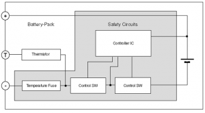
The battery terminals are generally labeled as : + , – , T , and D or Do.
T is connected to an internal temperature sensitive component ( thermistor) . This is to prevent overheating of the battery so it is very important on safety point of view
D or Do is a newly introduced contact. It is a data line which allows Smartphone and battery to exchange information about current, voltage, temperature, residual battery capacity etc…. It has been introduced to improve % remaining battery capacity readings.

Picture1fefPicture6


CEV - Handout