WHAT WOULD YOU FIND?
INTRODUCTION
WHY INSULATION SHOULD BE CONSIDERED?
THE TRANSMISSION LINE
BARE CONDUCTOR
INSULATED CONDUCTOR-UNDERGROUND CABLES
PARALLEL CONDUCTORS-OVERHEAD CABLES
ELECTRIC AND MAGNETIC CIRCUITS
TWO WIRE ELECTRIC FIELD
THE BREAKDOWN
CORONA (next blog)
NOTE: A BETTER EDITED VERSION OF THIS BLOG IS AVAILABLE IN ORIGINAL MS WORD FORMAT, LINK BELOW:
https://drive.google.com/open?id=1rvvbWubkvasvO_regM7QRSzcN5KWCW9g
INTRODUCTION
The generation, transmission, distribution and the consumption of electrical energy for the service of mankind is what in general the power system is supposed to do. If you had followed through the previous blogs in the electrical genre than it would be clear to you that in general, a power system comprises of sources of electricity i.e. the generators on one end and consumers of electricity like motors, heaters, and other appliances on another end, and between them is transmission and distribution system for efficient transfer of energy between components which are separated by huge physical distances.
- https://cevgroup.org/fault-analysis-and-related-technical-problems-in-power-system/
- https://cevgroup.org/blackouts-facing-the-outrageous/
- https://cevgroup.org/electrical-power-sytem-the-indian-frame/
- https://cevgroup.org/electrical-power-quality/
- https://cevgroup.org/the-electric-traction-indian-railways/
- https://cevgroup.org/menlo-parks-wizard-vs-the-serbian-american-inventor/
The aim of this blog is to understand the physics of dielectrics, explore the insulation systems of the high-voltage lines, and the associated phenomenon like corona discharge with them. And thereby imparting light on some of the problems of high-voltage engineering.
The transmission and distribution system has three very basic working parts: conductors, insulators and dielectrics. It seems that the conductors are real heroes, whereas insulators and dielectrics are not doing a great job here. However, in reality, the path of the flow of electrical energy is decided by the conductors, insulators and dielectrics equally. Also, to understand the difference between dielectrics and insulators reaching the end of the blog is necessary.
Why insulators and dielectrics should be equally considered?
The advantages of utilising high- voltage are many. Decreased line loss, efficient conductor use and better voltage regulation are names of few. Modern system uses a blood pressure as high as 132 kV, 440 kV, 765 kV, 1100 kV and the limit is rising. Increasing the voltage will indeed get you some cool results but it also has another facet to it.
“INSULATORS: I DON’T WANT TO BE INSULATOR ANY MORE”
Yes at these extra high voltages the insulators and dielectrics begin to give up their jobs and the flow of electric energy is no more defined and our power system goes in vain if required engineering is not performed.
THE TRANSMISSION LINE
Understanding the science of the insulation is all about decoding the distribution of electric field around a conductor.
A bare conductor:
Consider a conductor of infinite length, having Q charge per unit length. The electric field will be radially outward or inward depending on the polarity of charge. The field of lines go till infinity where we have assumed potential to be zero.
Plotting the electric field Vs the distance from the center of conductor:
NOTE: The electric field inside the conductor is zero.
Now, the voltage V and the distance relation: Assuming D as very large distance (infinity)
One more parameter is defined, the g, called the voltage gradient, mathematically its value is equal to the electric field and the unit is V per meter. From the expression, its maximum value occurs at the conductor surface always.![]() Let us check what happens when we fill the whole space with a dielectric of constant as εr2, keeping the Q on conductor value same:
Let us check what happens when we fill the whole space with a dielectric of constant as εr2, keeping the Q on conductor value same:
NOTE: gmax decreases proportionally.
And the voltage becomes:
Conclusion 1: Keeping the charge and all parameters constant, for increasing value of εr the magnitude of electric field and the voltage developed on conductor decreases. 🙄 WHAT?
An insulated conductor (the case of underground lines):
Now, let us see what happens when we reduce the dielectric material to some finite distance.
a.) Keeping the charge on conductor fixed:
In this case also the electric field will be radially outward or inward depending on the polarity of charge. But the field of lines will not go till infinity, it will terminate at the inner surface of insulator as we have grounded it (assumed potential to be zero).  Applying Gauss Law:
Again, plotting electric field (or g) Vs the distance from the center of conductor:
NOTE: Only finite termination of field at +D/2, magnitude remain same as for the infinite dielectric case.
Electric field and gmax remains same in magnitude but lesser than the first case.
Here D is finite. Hence, ln(D/d) term will be lesser, so less voltage developed.
Followed from earlier cases, for different insulators (increasing εr), we will see decrease in both electric field and the voltage developed.
Conclusion 2: For same charge on conductor decreasing the depth of insulation will lead to decreased voltage at conductor. 🤷🤐
b.) Now let us keep the voltage fixed:
- Effect of varying the material, (increasing εr);
To keep voltage fixed, the charge redistribution on the conductor will take place, charge will increase proportionally as we increase epsilonr2, ![]()
Analysing the electric field equation, we can easily see that the magnitude of field will not change,
Conclusion: At constant conductor to earth voltage the electric field (and the gmax) in the dielectric is independent of the material itself.
2.Decreasing the insulation depth in this case is extremely important case to consider, keeping in mind the expression of voltage and field:
NOTE: The electric fields will be limited to respective insulation diameter.
NOTE: Electric field is the gradient of voltage distribution, graph is in agreement of this also.
![]() Conclusion 3: At constant V if we go decreasing the insulation depth than the electric field will go on increasing and eventually will exceed a threshold limit.
Conclusion 3: At constant V if we go decreasing the insulation depth than the electric field will go on increasing and eventually will exceed a threshold limit.
HOMEWORK: Calculate for yourself the effect of changing diameter of conductor (d) on parameters.
We will use all these conclusions later directly in designing insulation systems later in the blog.
Two parallel conductors (the case of overhead lines):
Let’s have a revisit to the most general form of an electrical line.
Consider a pair of two infinitesimal small conductors at some potential and carrying some current. If we keep a paper in the plane perpendicular to the plane of conductors and sprinkle some iron fillings, we see a beautiful arrangement of fillings and we know they are along the magnetic lines of the system, as iron always align in the magnetic field.
Now suppose the conductors are only energised not carrying any current and the same experiment is repeated again with mica dust. What would we see?
Begin a dielectric material, the orientation of dust is different and they align along the electric lines of force of the system.
So whenever the power is being transmitted both of the fields are present and this fate of power transmission cannot be achieved if any of them is absent.
Across the whole length of transmission and distribution line, some energy is stored in two forms the electromagnetic and electrostatic field.
The behaviour and dynamics of these two fields can be studied using magnetic circuits and dielectric circuits respectively.
Let us go little off-topic to explore the magnetic circuits and dielectric circuits:
(WARNING: This goes far off-topic you can revisit this section later)
//THIS PARTICULAR SECTION IS UNDER-DEVELOPMENT
ANALOGIES
These two circuits have striking similarities between them.
Magnetic circuit:
- The magnetic flux in the set up by the magneto-motive force (mmf) developed by a coil carrying current.
- The amount of flux is restricted by the opposing parameter of the circuit called the reluctance which depends on the length, cross-section and magnetic property of the material.
- And the reciprocal of the reluctance gives the permeance.
Dielectric circuit:
- The dielectric flux is set up by the electromotive force (emf) of the source.
- The dielectric reluctance resists the flux, and reciprocal of it represents the capacitance of the dielectric component which is again a function of length, cross-section and the dielectric constant of the material.
|
MAGNETIC CIRCUIT |
DIELECTRIC CIRCUIT |
|
Magnetic flux, 𝜱 |
Dielectric flux, 𝝋 |
|
Magnetic field, B |
Electric field density, D |
|
Magnetic field intensity, H |
Electric field intensity, E |
|
Magneto-motive force, mmf |
Electro-motive force, emf |
|
Reluctance, R |
Dielectric reluctance, z |
|
Permeance, P |
Capacitance, C |
|
Absolute permeability, 𝝁 |
Absolute permittivity, 𝛆 |
|
Free space permeability, 𝝁o = 4π × 10−7 N⋅A−2 |
Free space permittivity, 𝛆o = 8.85×10⁻¹² F⋅m−1 |
|
Relative permeability, 𝝁r 𝝁r = 𝝁 / 𝝁o |
Relative permittivity, 𝛆r = 𝛆 / 𝛆o |
|
MMF= 𝜱R |
Emf = 𝝋z |
|
R = l / 𝝁r𝝁oA |
z= l / 𝛆r𝛆oA |
|
P = 1 / R |
C = 1 / z |
Other similarities:
- For higher permeability and permittivity of the material the magnetic and dielectric flux is higher respectively for the same mmf and emf.
- In the magnetic circuit, the major mmf drop occurs where the permeability is lesser similarly the maximum emf drop occurs in the section where whose dielectric permittivity is lowest.
TWO PARALLEL CONDUCTORS
Even if we don’t understand the field dynamics wholly still, we can at least attempt to apply our previous knowledge of the electric field and voltage distribution for two parallel conductors:
Qualitative description:
- Let +Q charge per unit length on surface conductor on right side and -Q charge per unit length on left hand side conductor.
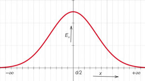
- These two will have electric fields which will add to produce the resultant field.

- Resultant field in
- (-∞, S/2): positive field will be dominant
- (@S/2): +ve field and the -ve field will exactly cancel each other at this point
- (S/2, ∞): -ve field will be dominant
Rough distribution of field be like:
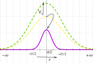
Votage distribution: Assuming zero potential at S/2 plane. If voltage between +ve wire came out to be V (from reference plane) then the voltage between conductor will be 2V.
Mathematically:
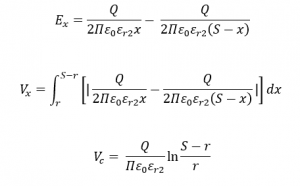
For region, (0, S)
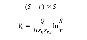
r being very small compared to S, so-
Simplifying E:
Substituting the value of Q:
Potential gradient is maximum at the surface:
NOTE: It is worth remembering IMP formula.
WHAT IS A BREAKDOWN?
The flux density which is dielectric flux per unit area when exceeds a limit the insulation or the dielectric material also starts conducting and electrical energy is wasted, this point is called the breakdown or puncturing of the dielectric or insulation.
Each material has its own limit of withstanding high-voltage without getting punctured. The strength of insulation is generally expressed in terms of gradient rather than flux density.
Note: There is no relation between the dielectric strength and the dielectric constant of the material.
Here also the dielectric system could be understood by taking the actual mechanical system as an analogy.
Whenever a material is loaded with some force there is deformation, the energy gets stored in material, and these characteristics are represented by the elasticity of the material. Each material has is the ultimate strength after which it breakdown.
Similarly, the potential gradient might be thought of as the force then the flux density as resulting electrical strain, and here permittivity is the electrical elasticity. The energy is stored with increasing force and is given back with decreasing voltage. Rupture occurs when a unit force exceeds the limit.
This concept can be used to easily understand why a highly permeable material when taken in series with a low permittivity material the later one gets ruptured first. As in the mechanical system, the stiffer material (lower elasticity) takes up the major stress and breakdown first.
Breakdown in air i.e. Corona will be explored in detail in next blog.
Sometimes it isn’t enough to just read about it, you have to interact with it! And that’s exactly what you do when you use one of blogs of CEV!!!
You can involve in a technical discussion with our electrical folks:
- Anshuman S Jhala: singhanhuman88245@gmail.com
- Vartik Srivastava: vartik17802371@gmail.com
- C. Vamsi: samvamsi2000@gmail.com
- Rahul: rahul14kumar20@gmail.com
You can drop some suggestion for improvement, and contribute by sharing your wisdom on following two questions for developing the #Analogies Section.
- HOW TO FIT INDUCTANCE INTO THE PICTURE OF MAGNETIC CIRCUIT AND CO-RELATE WITH THE ELECTRIC CIRCUIT?
- HOW TO ESTABLISH LINK BETWEEN ELECTRIC FIELD AND MAGNETIC CIRCUIT MORE STRONGLY PARTICULARLY FOR THE TWO WIRE SYSTEM?
REFERENCES
Drive link:
https://drive.google.com/open?id=1O08y5BKftYHkTY6ZeUrKIQd3S-cGQ776
Keep reading, keep learning
TEAM CEV!


