Terrorism is very scary, especially when it happens close to home and not in some faraway place. Nobody likes to be afraid, and we were eager to make the fear go away. So we demanded more security. In the last decade, it’s become increasingly normal for civil liberties to be eroded and for government agencies to spy on citizens, to collect and store their personal information. Regardless of whether you’re a fan of right- or left-wing policies, this affects every one of us.
So we have to take a look at the data and ask ourselves honestly, “Has all of this actually made us safer?”
The Beginning
After the attack of 9/11, the US government concluded that the law had not kept pace with technology. It created the Terrorist Surveillance Program initially to break communications linked to al-Qaeda. Officials were confident that if the program had been in place before 9/11, the hijackers could have been stopped. But soon the new powers were also used to prove guilt by association.
The FBI used immigration records to identify Arab and Muslim foreign nationals in the US. On this basis, 80,000 individuals were required to register, another 8,000 were called in for FBI interviews, and more than 5,000 locked up in preventive detention. Not one terrorist was found in this campaign.
In 2013 Snowden leaked the document that reveals how the government sees and stores the private data of public. They showed how the NSA(National Security Agency) can demand information about users from companies like Microsoft or Google in addition to their daily collection of data from civilian internet traffic such as email content and contact lists. So, instead of focusing on criminals, governments are increasingly turning their attention to everyone. But if you are looking for a needle in a bundle of grass, adding more grass to the bundle isn’t going to make it any easier to find the needle.
On the contrary, every recent success announced by the NSA has come from classic target surveillance. Despite high hopes, the NSA surveillance program has not stopped any major terror attack.
Apple Vs FBI
In early 2016, the FBI asked Apple to produce a backdoor program to disable the encryption of a terrorist’s iPhone. Apple publicly declined, not only because this tool could be used to permanently weaken the privacy of law-abiding citizens worldwide, but fearing to open the floodgates for governments requesting access to a technology used by billions of people, a fear shared by security experts and cryptographers. A few weeks later, the FBI revealed that they had hacked the phone themselves, basically admitting that they lied to the public about the need for a backdoor, which questions how trustworthy spy agencies are in the debate about privacy and security, especially considering that the NSA, for example, already has the capability to turn on your iPhone microphone or activate your laptop camera without you noticing. Concerns about this are often met with the argument,
“If you have nothing to hide, you have nothing to fear.”
But this reasoning depends on person to person because if a person wants to keep privacy about own life then it doesn’t mean he/she is doing anything wrong. Right now, we live in a democracy. But imagine the damage the wrong person could do with our data because data is the new treasure of the current world.
The Government uses this law for own benefits
For example, following the November 2015 Paris attacks, France expanded its already extensive anti-terrorism laws by giving law enforcement greater powers to conduct house raids and place people under house arrest. Within weeks, evidence emerged that these powers were being used for unintended purposes, such as quashing climate change protests. The governments of Spain, Hungary, and Poland have introduced more restrictive laws on the freedom of assembly and speech.
If we talk about the FBI, then there is a case of former FBI director James Comey used this NSA data for his personal use.
There is also a case of Cambridge data analytica.
Indian Cases related to Data privacy :
Now if we talk about the case of India, this data privacy issue first come is light when aadhar card details were easily available. In Supreme court hearing Unique Identification Authority of India(UIDAI), the agency implementing aadhar repeatedly argued about Aadhaar that It will help against terrorism and banking fraud by ensuring that only “genuine” persons get access to mobiles, and banking services but in reality, the bank fraud cases were increased.
There is also a big question about how these aadhar card can be misused? Adhar card become more dangerous when other documents linked with aadhar. Imagine a third party hacker can access all your data like biometrics and bank account details then he can damage you in a bad way.
None of this is effectively helping us fight terrorism. The motivation behind this might be good, even noble, but if we let our elected governments limit our personal freedom, the terrorists are winning.
Then what is the Solution?
What’s worse, if we’re not careful, we might slowly move towards a surveillance state. The data is pretty clear: the erosion of rights, along with mass surveillance, hasn’t led to significant successes so far, but it has changed the nature of our society.
Terrorism is a complicated problem…
…without simple solutions.
No security apparatus can prevent a few guys from building a bomb in their basement. Creating master keys to enter millions of phones is not the same as searching for a single house. To take full advantage of this existing condition, we need better international cooperation and more effective security and foreign policies, better application of our present laws instead of new and stricter ones that undermine our freedom. We live in Democracy and we have our rights in our hands.
This series covers some of the popular methods of consensus being used in current public blockchain networks.
Before diving deep into the stream. To make things more clear, let’s understand which type of consensus protocol can be used in case of public blockchain networks.
In the case of permissioned blockchain, actual message passing (gossiping) takes place between the participating nodes. So nodes are known to each other in such networks.
Contrary to this, in public blockchain networks, any node can join or leave the network anytime. So nodes are anonymous to each other and to reach a decision, leader election will always take place in reaching the consensus.
The leader will decide what will be the next block and other nodes can easily validate the new proposed block.
At the end of the article, if you feel confident to explain the term to others, then don’t forget to leave claps behind.
Proof of Work(PoW)
This consensus algorithm is quite popular and used in many blockchain networks like Bitcoin and Ethereum.
To understand PoW in a better way, let’s discuss a few more terms:
Mining: It is the term given to the event of adding a new block of transactions to the blockchain. In public blockchains, a leader is elected who will decide what will be the next block. The elected leader is called “Miner” and the process of adding the block is called “Mining”.
Hash: A hash function is any function that can be used to map data of arbitrary size to fixed-size values — Wikipedia
Nonce: A nonce is a random number in cryptography which is used only once. In the context of Blockchain, the miners hash the block data and nonce to reach a target in a brute-force manner.
Let’s know more about Transaction Life-Cycle in Bitcoin Network-
Each transaction is added to the transaction-pool first.
From transaction-pool, different participating nodes take input the transactions and compete with each other to mine the next block.
The node which solves the problem first wins and decides what will be the next block.
So, the first question you might be thinking must be- How does the leader gets elected? Who will decide what will be the next block since different miners who are competing will have different transaction list due to the network delays? Don’t worry, Let’s catch it up together after reading a few more things.
During the consensus process of PoW, the complex mathematical problem selected is such that it is very hard to solve but very easy to verify.
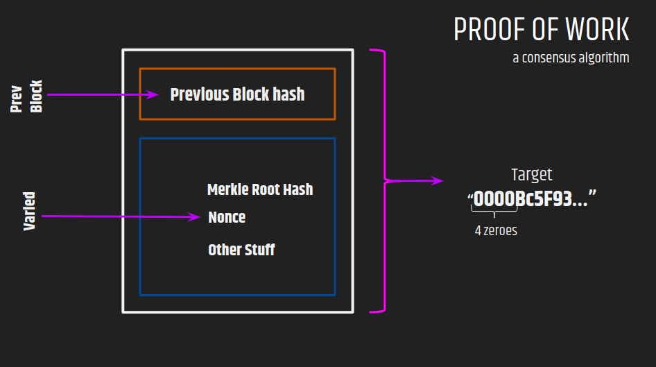
For example- in the case of the Bitcoin Network, the problem is – the generated block hash should have the fixed number of zeroes in the beginning. e.g the target Block-Hash should have 12 zeroes in the beginning.
So in the transaction life-cycle, different miners collect transactions and generate a new block and try to solve the complex mathematical problem. The miner who solves the problem first gets the chance to broadcast his block to the rest of the network, where it can be verified easily.
Moving forward, we are talking about ‘complex’ mathematical problem. So what exactly it is?
Before this, we need to understand how the block hash is actually generated. Let’s see the case of Bitcoin:
As already mentioned, different miners collect transactions from the pool. After that, they generate the Merkle root hash from the list of transactions. This is done by hashing the transactions in a pair-wise manner repetitively.
Merkle Root
This ‘Merkle Root Hash’ along with the ‘previous block hash’ and ‘nonce’ constitute the ‘Block Header’ of the block. The ‘Block Header’ is then hashed with few more fields present in the block to generate a unique identifier of the block, called ‘Block Hash’.
Say, the target problem is- to generate the block hash to have initial 4 number of zeroes. Then to solve this problem, each miner will vary the nonce, so that generated block hash meets the target.
The solution to this problem is complex as it can only be achieved through a brute-force approach by varying the nonce. A huge amount of computational power is spent in finding the right solution which meets the target.
Another amazing point is that, the difficulty of the complex problem(how much initial zeroes), is set according to network demands and transaction throughput of the bitcoin network.
So, now you can imagine just to add a valid block, a huge amount of computation is done. The tamper-proof characteristic of blockchain is somewhat supported by PoW. If someone tries to intrude any transaction data in the block, then its Block Hash becomes invalid and since in blockchain each block holds the hash of the previous block too, so hypothetically we say the chain breaks, and to restore the things the attacker needs to recompute the Block Hash of all the subsequent blocks from the block in which he changed the data till the most recent block, or we can say the attacker has to do the work again. All this will require a huge amount of computational resources which may worth very less than the value of data.
The only motivation for the miners to participate in Bitcoin mining is rewards. The miner gets reward for proposing a valid block and this reward is in the form of newly generated/mined bitcoins in the network.
That’s it, this is the short explanation of PoW from my side. Keep hustling to understand it till you are not satisfied.
This short-article focusses on one of the most popular consensus problems in distributed computing known as “Byzantine’s General Problem” and when a distributed system is said to be Byzantine Fault Tolerant.
Various Byzantine Fault Tolerant algorithms are being used in Permissioned Blockchain Networks e.g Hyperledger Sawtooth is using Practical Byzantine Fault Tolerant(PBFT) to achieve consensus. So, if you want to understand how the consensus is actually achieved in such systems. This article is surely for you.
So let’s begin this journey.
First of let’s focus on the term ‘Byzantine Fault Tolerant’ and when a distributed system is said to be Byzantine Fault Tolerant?
The answer lies within the different types of failures that can occur in a distributed system-
1.Crash-Fail: In this type of failure, the component stop working without any warning. So you need to restart the node or replace it. We can say it is a ‘Fail-Stop’ failure.
2.Omission Failure: In this, component transmits a message but that message is not received by other nodes or we can say it is omitted.
3.Byzantine Failures: It is a ‘no-stop failure’.It occurs when there is a malicious or traitor node in the network which sends conflicting messages or block the messages by not sending them to the other nodes in the network, which may lead to faulty results.
Now I think it is self-explanatory that a distributed system is said to be Byzantine Fault Tolerant if it can cope-up with the Byzantine Failures.
The applications of BFT can be found in various domain like Blockchain and even in Boeing 777 and 787 flight controls.
Let’s move on to a specific problem which forms a base for understanding BFT-
The Byzantine General’s Problem :
Situation: Suppose there are several generals and they have to attack army camp C and they are surrounding the army camp such that they can’t communicate with each other directly. The only way communication can happen in between them is through a carrier and he needs to pass the enemy camp for transferring every message.
So they need proper protocols to reach a final decision whether to “attack ” on C, the next morning or “retreat”.
If they all agree to attack, and they do attack then they will surely win or if they agree to “retreat” then they can fight on another day. But if one of the general attack and other decides to retreat then they are surely gonna lose.
Problems:
Malicious Generals create variation in the decision to the others
Message Carriers may not reach
Reach a single solution, considering the downsides of a few Generals
Keeping in mind the situation, let’s discuss this problem with three generals.
Three Generals Problem:
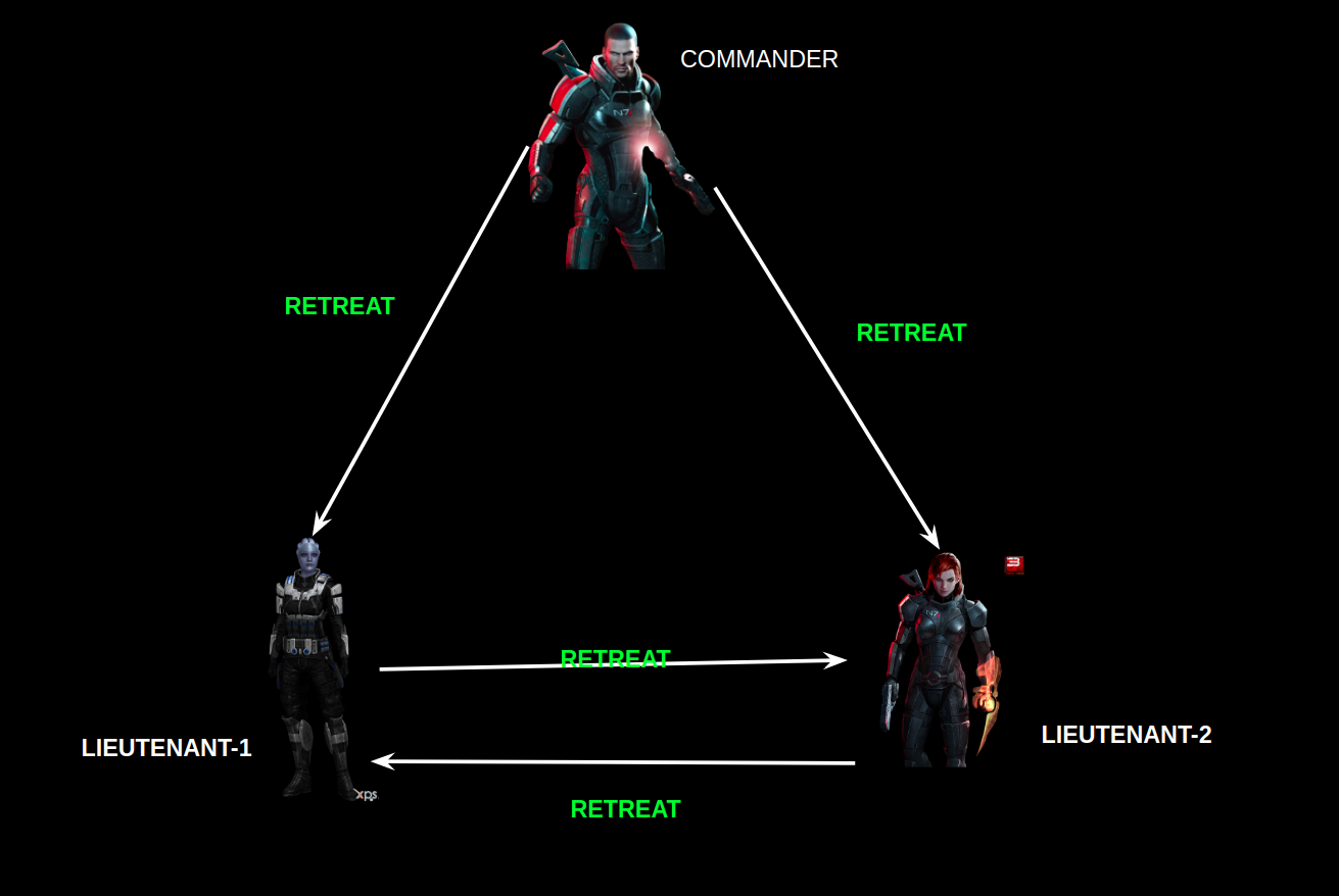
Suppose, there are one commander and two lieutenants surrounding the army camp C and they have to collectively reach a decision to ‘attack’ or ‘retreat’.
If neither of the generals is faulty then all will work good and they will surely reach a decision.
Let’s see the case if one of the generals starts behaving maliciously:
Let’s break up the whole communication process in two phases.
Phase-1: Commander sends the messages correctly to lieutenants.
Phase-2: Lieutenant-1 correctly forwards the message to Lieutenant-2.
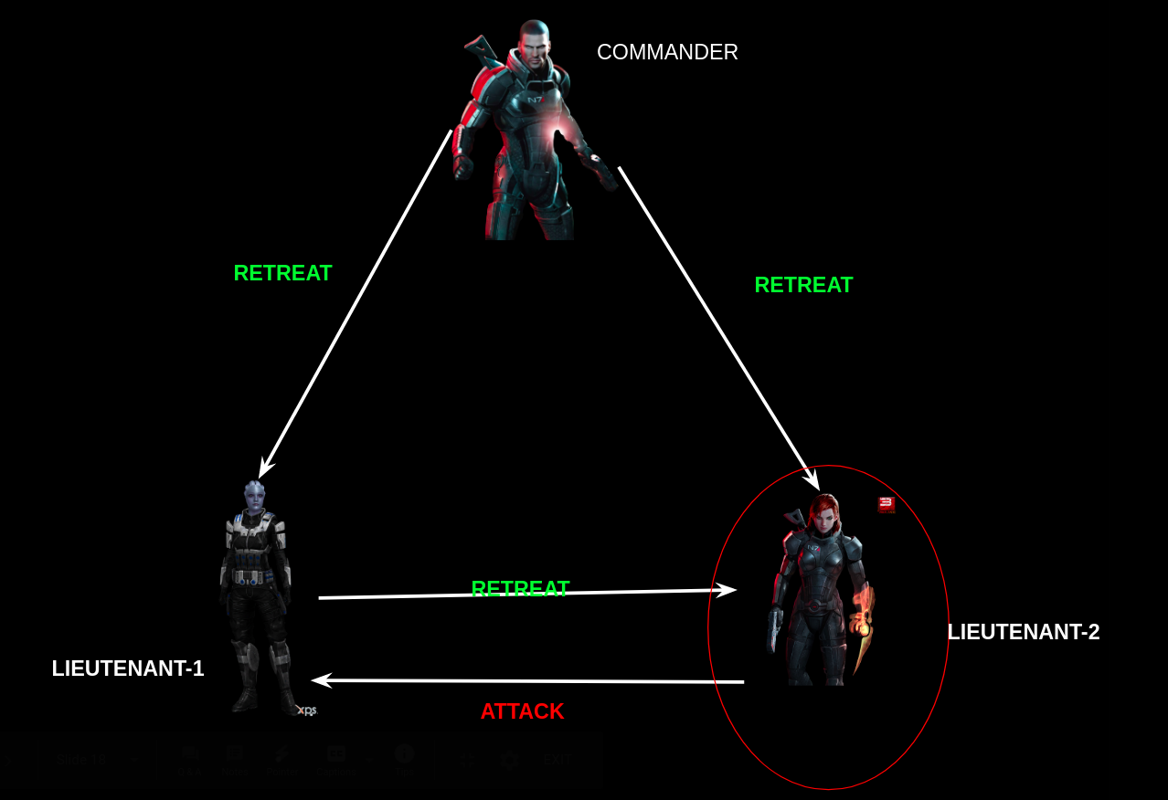
As Lieutenant-2 is malicious, so he forwards the message to Lieutenant-1 incorrectly.
Clearly, Lieutenant-1 is receiving differing messages.
Let’s take a look at another possibility before jumping onto the conclusion.
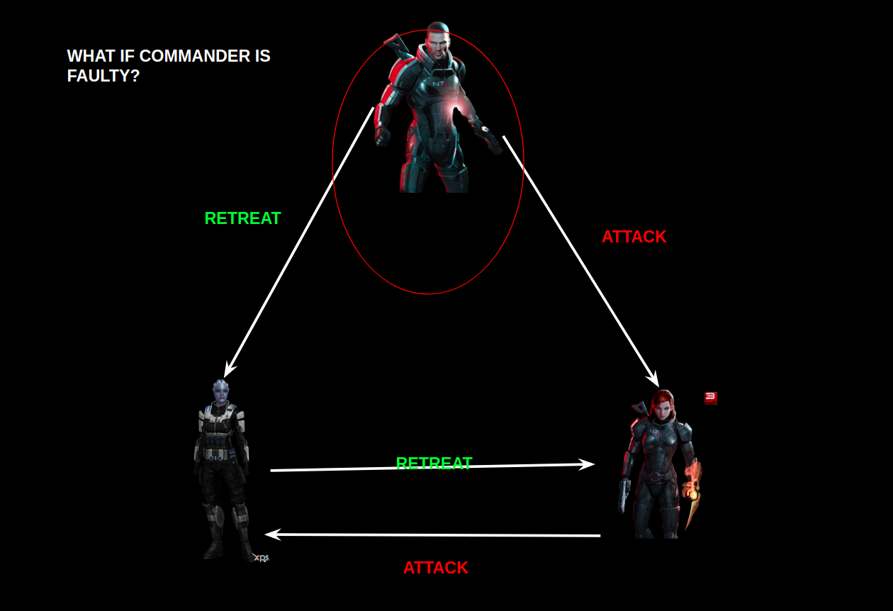
What will be the case if ‘Commander’ is faulty?
Phase-1: Lieutenant-1 and Lieutenant-2 recieves different messages.
Phase-2: They both exchange the messages correctly as they are loyal.
As per the protocols, both Lieutenants have to follow the Commander’s message. This is in the contradiction of the agreement condition.
Conclusion: There is no solution possible for ‘Three Generals Problem’ if one of the generals is faulty.
Four Generals Problem
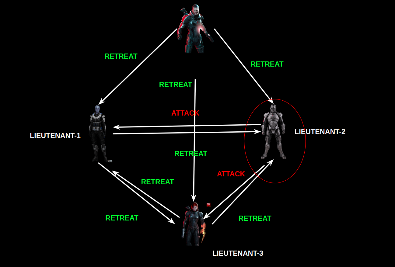
Suppose, there are one commander and three lieutenants surrounding the army camp C and they have to collectively reach a decision to ‘attack’ or ‘retreat’.
When one of the Lieutenant is faulty?
Phase-1: Commander correctly sends the message to other lieutenants.
Phase-2: Lieutenant-1 & Lieutenant-3 correctly forwards the message to others.
Lieutenant-2 behaves in a byzantine manner and incorrectly transmits the message.
By Majority Voting, the non-malicious lieutenants can reach the decision.
Decision of Lieutenant-1:
Majority(Retreat,Attack,Retreat)=Retreat
Decision of Lieutenant-2:
Majority(Retreat,Retreat,Attack)= Retreat
So, they have reached the consensus i.e “To Retreat”.
When the Commander is faulty?
I think you can deduce what will happen in the two phases now.
Jumping directly to the decisions:-
Decision of Lieutenant-1:
Majority(Retreat,Attack,Retreat)=Retreat
Decision of Lieutenant-2:
Majority(Attack,Retreat,Retreat)= Retreat
Decision of Lieutenant-3:
Majority(Retreat,Retreat,Attack)=Retreat
So, the consensus has been achieved with the decision “To Retreat”.
One more special thing to observe here is that the final agreement will be the one which is in the majority of the decisions in Phase-1 e.g Retreat is in majority in Phase-1. So final agreement is on “Retreat‘’.
Conclusion: If out of 4 generals, only one is faulty or behaving in a byzantine way, then we can reach the agreement and consensus is achieved.
By the above two scenarios, we can now generalise the Byzantine Model of Distributed Systems.
Generalization
A System having ‘f’ number of faulty nodes(generals) should have at least, in total 3f+1 nodes(generals) in the network to reach the consensus.
Thanks for showing patience and reading until the end.
Next in the series is ‘PBFT & RBFT Consensus’ and ‘Consensus in Public Blockchain Networks’.
We have got in our head what is electrical breakdown means actually, refer to the previous blog if not!
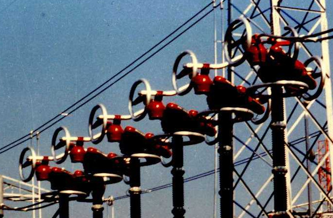
The puncturing of the porcelain or polymer insulators is quite rare however the air the major insulator in overhead line give up quite easily if care is not taken. The breakdown of air is a phenomenon called corona discharge. In High-Voltage transmission (HVDC and HVAC) this becomes a critical design consideration. Why?
We find description of this phenomenon as early as 1920s in Peek’s foundational work, electric utilities have been extensively researching on it for past 50 years, still we have not uncovered it much clearly and completely. However, modern system does manage to effectively tackle the corona problems and, in this blog, we will see all about it.
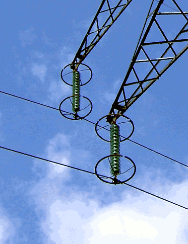
A visual introduction would be very helpful to begin the topic:
A luminous discharge due to ionization of air surrounding a conductor due to electric flux density (or voltage gradient) exceeding a certain critical value is called corona discharge.
We had already seen the distribution of the dielectric field, and we also know that the points at which it exceeds the flux density limit (30 kV per cm for air) the air starts conducting.
PHYSICS OF PHENOMENON: WHAT IS GOING DOWN THERE?
In general, any type of corona can be explained in following layman language:
Ionization and excitation: Though the air is neutral fluid but there are many sources which don’t allow it to be. The UV radiations from Sun, the Cosmic rays from space, the gamma rays from radioactive decay in soil are major sources for air ionization. These natural ionizing events create 20 ion-electron pair/cubic cm per second.
Electron accelerates: As soon as the potential gradient threshold limit is surpassed at the surface, it becomes capable to impart enough kinetic energy to the electron, generated from the ionization.
Collision and Avalanche: The energetic electrons collide with neutral gas molecules and knocks out electrons and effect become cumulative, leading -to formation of a conducting air, the plasma.
Drift out: Soon the electrons move out of range of high potential gradient and become less energetic and avalanche fades.
Recombine: The electrons slowly find positive ions and recombine to emit light in visible or UV region, they also initiate chemical reactions leading to formation of ozone, etc.
Note: Not all recombination takes place far away from conductor, they also occur in plasma region.
Now, the polarity of charge on the conductor significantly changes the process.
POSITIVE CORONA
When conductor has positive change:
The electrons generated in plasma region are immediately drifted inwards, thus electron density in vicinity of conductor is lesser.
of electrons are less but majority of them are in region of high potential gradient, hence the average energy of electrons is high.
These electrons cannot support (or initiate) low energy chemical reaction.
The high energy level of electron gives the phenomenon its characteristics emission of blue light or UV radiation.
NEGATIVE CORONA
When conductor charge is negative:
The electron generated in the plasma region is repelled outwards, so as a result, in this case, large no of electrons in vicinity of conductor is observed.
However, more electrons are concentrated in region far way from conductor surface, in low potential gradient hence are in low energy state.
Due to low average energy of electrons, inelastic collision with neutral molecule don’t contribute significantly in avalanche as do the knocking of electron by photons (photoelectric effect) emitted from the recombination taking place in high potential gradient region of plasma.
Ozone production is a relatively low energy process, average energy electrons in negative corona are perfect initiator.
The energy state is also responsible for the characteristic red color of discharge. (Note: Red is low energy radiation compared to violet or blue)
+VE CORONA
-VE CORONA
Less no. of electrons
More electrons
Highly energetic electrons
Low average energy state
Avalanche produced by inelastic collision
Avalanche produced by photoelectric effect
Blue-violet uniform glow
Red glow
Less ozone
More ozone
NOTE: Modes of corona have been further classified based on voltage level. Research paper on the same is listed in references.
EFFECTS
Now corona have observeed to produce the following effects:
Light emission:
The recombination of electrons with positive species emit characteristics electromagnetic-waves. More on that later.
Radio Noise:
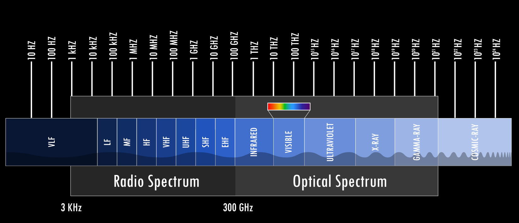
Experimental data have shown that the corona current is pulsating in nature. We haven’t found out yet! The frequency of this current lies in wide range of order of MHz, large part of which lies in our defined radio frequency band.
This current produces two unwanted effects:
This high-frequency corona current, called harmonics adds to load current of transmission line and cause distorted current and voltage sine waveforms, highly undesirable. In layman terms, it is called power pollution.
Bound by laws of physics they produce electromagnetic waves in rf band, which interfere with the telecommunication signals. Depending on the distance, orientation, and several other factors the effect ranges from negligible noise to complete distortion of the communication signal.
Note: The radio waves and light emission are occurring on the same physics rules.
Audible Noise:
Energy discharge is occurring in form of fast-moving particles in air. And audible noise is nothing but pressure disturbance in air created by motion of air particles. Corona discharge sounds like a hissing, low amplitude and occurs over wide frequency spectral range.
4. Chemical effects:
The ionized electrons start a cumulative process of forming electrically charged species. Oxygen atoms are major neutral atoms to form radicals O, which then combine with O or O2 to form O2 or O3 respectively. The reactive nascent oxygen also combines with metals and organic matter. The reactive ozone under extreme electrical stress might also react with stable nitrogen to form oxides. The ozone also reacts with insulation material, corroding them slowly, leading to damage without a sign of warnings.
Moreover, over a certain concentration ozone has proved to be toxic to life.
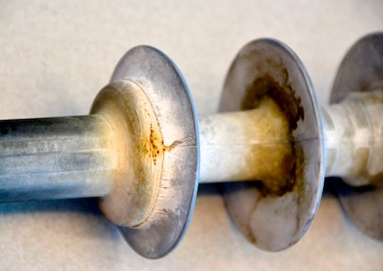
All of these are confirmed by many shreds of evidence like the smell of ozone, deposition of white powder, and worn out insulators.
The insulation degradation is additive effect of corona and other environmental factors
Power loss:
All of these effects which include light, radio waves, audible waves generation and also, heat produced, lead to a waste of energy. To calculate the corona power loss, we have some methods and empirical formula, none of them with error less than 30%. Which marks the complexity of corona discharge!
Conductor vibration:
The effects mentioned above are monitored to determine the corona performance of any transmission lines. However, a weird, not much considered effect is also there, mechanical vibration of conductors.
The wires under tests for corona noticed to vibrate in fundamental and other harmonics.
AC and DC CORONA
**Contribute
HVAC
HVDC
Poor foul weather performance
Better performance in foul weather
More radio interference and audible noise
Reduced RI and AI in wet weather
MATHEMATICAL DESCRIPTION
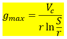
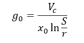
We have already calculated the potential gradient distribution in space for parallel conductor case and we also know that it is maximum at the surface of conductor.
And is given by,
For a given conductor spacing, and given voltage level, the potential gradient obtained at the surface will be constant, independent of any other external factors.
Now, the maximum dielectric stress that could be handled by air is g0, 30 kV/cm.
How come?
We know the distribution of potential gradient:
Maximum voltage that could be applied is:Let us see that if it is true that the corona always begins as soon as the potential gradient, g0, i.e. 30 kV/cm is reached at surface? Or the air can withstand more or less?
The question is reasonable because it has been observed for same voltage level and conductor arrangement, system have shown different corona characteristics. Negligible corona in dry summer but effect multiplies 100X in foul weather/rainy season.
Effect of conductor spacing:
Question is same like: does the elastic limit of a rod depends on its physical dimension like its length. Clearly the rod always breaks at the same unit stress, no matter how long or short it is, so does the air’s dielectric strength is independent of conductor spacing. (Assuming air as a rod)
Effect of conductor diameter:
It’s a well-established experimental fact that the air is apparently stronger at surface of small conductor, for same conductor spacing the potential gradient at surface of small conductor for onset of corona is greater than 30 kV/cm.
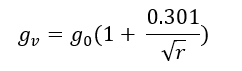
So, air breakdown potential gradient at surface is gv not g0, so the equation becomes:
Let us call gv as apparent dielectric strength of air.
The experimentally calculated formula for the minimum potential gradient at surface to start corona is:
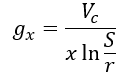
Now, let us suppose that occur at from the centre, so:
It comes out that g0should always be occurring at distance of 0.301sqrt(r) from surface of conductor not at the surface of conductor. At surface there should be some higher value, gv.
These terms however become insignificant for larger diameter conductors.
People have tried to explain the phenomenon using different theories, among them best suited is the electron theory.
“The 30 kV/cm is limit just sufficient to accelerate the electron over its mean free path to acquire as much as energy to form ions by collisions. The electrons would require some finite distance to get sufficiently energetic, on the other hand, the potential gradient from the surface goes on decreasing hyperbolically. Thus, greater potential at the surface of conductor is required than the dielectric strength of air, so that electrons get enough time (distance) to get enough kinetic energy.
Here rises a very intriguing question, and it is, would corona will not take place if we keep the conductors spacing less than 0.301sqrt(r).
Its is quite amazing to know the answer as big “YES”.
The experiments have shown that the same fragile air, in experimental setups of small air spacing has been made to withstand gradients as high as 200 kV/cm.🤐🤐
Then why we don’t hang our wires as close as possible? 🙃
Note 1: It should be noted here that the 0.301sqrt(r) distance is several times greater than the mean free path, so the electron undergoes many collisions before actual ionizing collision. It is only after accelerating for this distance the electron gain required K.E. To get real clear, a dive into the depths of Kinetic theory of gas is required.
Note 2: When we are talking of ionization of air in actual it is the oxygen which is being ionized to form highly chemically active O, (30 kV figure is respect to that only). The radical than combines with different ions to form ozone, oxides, etc. depending on its energy level.
Air density: Effect of temperature and pressure
Does the temperature and the pressure also have influence on the g0 and gv?
Yes!
Different high voltage transmission systems (HVDC/HVAC) have shown an increase in corona loss from 3 to 100 times in foul weather than in clear sunny day. This indicates that meteorological conditions affect the g0 that’s why corona intensifies for same system and same voltage level.
We know that the for decreasing air density the intermolecular spacing will widen, which also implies that mean free path of electrons will increase, thus potential gradient (g0) required decreases, with decreasing air density.
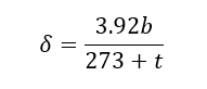
δ is the relative density.
Using, the ideal gas equations, the ratio of density is calculated at two different temperatures and pressure, reference taken as 25° C and 75cm pressure ( δ is taken as 1). (PM=dRT)
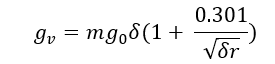
But this proportionality relation seems not applicable for the gv, thus the equation was taken of form:
Repeated experiments, and fitting the results led to revealing f(δ) as:
So,
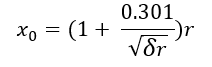
and the new accelerating distance becomes:
Accelerating distance increases with decreasing density. WHY?
We at CEV also cannot figure out, share with us if you can.
Conclusion: For decreasing air density the dielectric strength of air decreases proportionally, whereas the apparent strength also shows a non-proportional decrease.
Effect of Conductor surface:
To consider the effect of surfaces on corona discharge becomes of crucial importance when designing any product like connectors, spacer dampers, markers, end lockers, etc for high voltage applications.
To get an intuition of how the surface would impact the corona discharge, consider a uniform sphere being excited by high-voltage, for any voltage level the electric lines of force in air (or dielectric lines) around the surface on conductor is uniformly distributed. Now if we excite a metal sample which has non-uniform sharp corners then would the field distribution remain uniform?
The answer is no.
Various techniques are employed to find the rough distribution of electric field around the products, most viable is the FEM technique. This Finite Element Method (FEM) is used more popularly in civil and mechanical engineering, in visualizing the stress, compression and tension and identify the weak and vulnerable points in their structures.
Those same FEM techniques are used to get computer models simulations of the product to identify high potential gradient points.
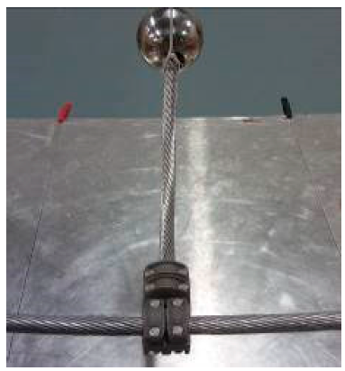
Let see the result of a study for a HV hardware manufacturing company which exactly proved these theories using the FEM techniques. (refer 123)
This specimen was specimen for the studyThis was the computer-generated model
The radius of curvatures at finite elements (mm)FEM simulation of potential gradient at the surface (kV/mm)
It comes out that the points with sharp edges (high radius of curvature) has high degree of concentration of field lines thus greater potential gradients and are points where dielectric strengths are first crossed.
When tested for corona performance of the connector the results were as expected.
Conductor being excited until corona was observed
Visuals confirm that the points predicted by simulation came out to point sources of corona.
To take the effect of surface roughness there is an irregularity factor, m. So, the apparent dielectric strength becomes:
m is 1 for smooth surfaces
Conclusion: If the conductors get weathered over time and develop rough surfaces, the corona will start at lower voltage levels, at the sharp edges.
Finally, the expression for voltage level at which corona will begin for parallel wire is:
REMEDIES
Corona discharge is highly undesirable in transmission lines because of the effects it produces. An average yearly loss for ±500 kV HVDC line is estimated to be around 25W/m, which is considerably large if summed over a year for larger distances. Included with radio interferences in telecom signals, noise pollution, emission of ozone which degrade the insulation and have toxic environmental effects, the corona discharge becomes a costly affair!
The current majorly employed techniques to check corona are:
Bundled conductors:
Bundling of conductors is the most effective and widely used techniques, to decrease the potential gradient on conductor surface for a given voltage level or in other way to increases the corona inception voltage and thus improving the corona performance of a transmission line.
For increasing voltage levels two, four, six and sometimes eight stranded conductors per phase are bundled using spacer damper at regular intervals are employed. These dampers keep in check that the conductors maintain required distance during high-winds.
Now the actual question to be answered is how the potential gradient at the conductor surface decreases for a system of bundle conductors. The computation of electric field for a bundled arrangement can be done using numerous available mathematical tools.
Various research papers have used techniques of conformal mappings, simulated charge methods, FEM, integral equations, and other methods to calculate the field distribution much accurately.
Here let us use basic superposition method to conclude that the gradient decreases for bundle conductors.
Consider a single conductor of radius r, at voltage V from a plane at relatively large distance D.
Equations of electric field in space, conductor voltage and charge are as follows:
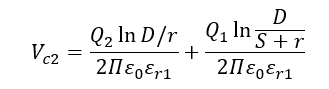
Now if we take two conductors at same voltage separated by a spacing S, then charge redistribution takes place.
Let Q1 and Q2 be charge on conductor 1 and 2 respectively:
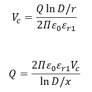
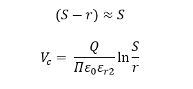
Potential at surface of conductor 2 is (by integrating electric fields along x-axis):
Similarly, by geometry potential at the conductor 1 surface is:
Now as we know-
Which leads to-
So, the potential becomes:
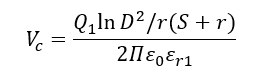
Assuming S≈r,
Since we are computing for same voltage level, clearly-
If not accurately, we can surely say that:
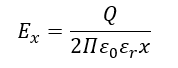
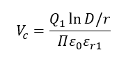
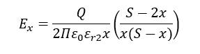
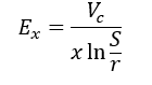
Now calculating the electric field at the surface of conductor 2:
Solidly we can conclude from the above expressions that the potential gradient decreases with adding more conductors in for one phase.
More accurate methods of calculation are given in references xx and yy.
Here are graphic simulations of electric field calculated for single, two, three and four conductors.
Notice how the gradient decreases for increasing the no of conductors in a bundle.
For three and four conductors bundle field even decreases more:
Another important point to be noted is that the dependence of potential gradient is not linear for a given no of conductors in bundle. The potential gradient is a function of bundle geometry and achieves minimum value only for a particular value of bundle radius (conductor spacing).
Potential gradient at the surface of bundles different no of conductors(N) and different bundle radius
Note:
All the corona performance parameters like loss, radio interference, audible noise, etc. seemed to improve considerably for bundled conductors.
Further study would reveal other advantages, like:
Better thermal properties, better cooling due to increased surface area
Reduced line inductance
Increased transmission capacity
However, wind and ice loads are greater for this arrangement, and also complication in designing and placing spacers is there.
Corona Rings:
Another effective remedy has same underlining principle of redistribution of electric field lines such that the potential gradient limit is exceeded only at few points!
Use of curved smooth metal rings (shown above) called as corona ring connected to the high voltage hardware reduces the gradient on conductor surface by redistributing field in more uniformly.
FEM simulation confirms the same:
The red regions (relatively sharper) have high potential gradient as act at point source for corona discharge, when electrically connected with the corona ring the field lines become uniform in space, hence improving the corona performance. In this particular case, they also improve the voltage drop distribution in the insulator strings, when used also for this purpose they are technically called grading rings for insulators.
When used specially for conductors (HV apparatus) they are called corona rings.
Nearly all the hardware of high voltage transmission system uses corona rings:
1. Corona rings safeguarding the sharp junction points of conductors and insulator and also improving the string efficiency:
2. Circular corona rings on the switch gears at the HV substation:
Smoothening:
We have already seen in the that the electric field exceeds the threshold limit first at the sharpest points due to greater concentration of lines. So, transmission line components are designed to be free of sharp edges and rough surfaces.
DEMONS CAN ALWAYS BE TAMED! JUST USE SCIENCE
Somewhere in the early 1900s, an experimental scientist Birkeland’s high voltage electric gun demonstration model failed due to short-circuited followed by an arc. But soon he realized that the arc generated could be utilized for some useful purpose. Backed by businessman S Eyde he went on discovering a process you all would have heard of- the Birkeland-Eyde’s process for manufacturing of fertilizers. Since then these gas discharges have been used for industrial processes.
Even though the mysteries of electrical coronas remain largely undiscovered yet this phenomenon have found its applications into many crucial fields. These days corona is used for industrial chemical synthesis, photocopy machines, surface treatment, air pollution control, bactericidal applications, in fact they have even proved to improve the insulation, and many others.
Let us divide this section into two parts, application already being used and applications in which research is going on.
PHOTOCOPIER: It is pretty weird to know that we, electrical engineering student’s whole semester visualized corona as devil and in the end comes out to be principle behind our lifeline. 😅😅😅
AIRCRAFTS
OZONE PRODUCTION
Under-research applications:
AIR POLLUTION CONTROL
ELECTRICAL INSULATION
CONCLUSION
The scientific community along the industrial partners have been exploring Corona discharge for a long time, however due to complexity of phenomenon it has largely remained undiscovered and untapped.
Extensive research for HVDCs:
It has now become an absolute necessity to tap the renewable energy from coastal, offshore, and other remote location to keep up with ever-growing energy demand. HVDC system not just provides a gateway to transfer that large power to large distances by integration of renewables on the grid but also comes with great operational benefits of better efficiency, increased stability (no need of synchronism), reduced right of way and what not.
And in these times when HVDC projects are popping up across the globe, not many high-voltage industry companies share high-expertise in HVDC technology as they have in HVAC. Corona remains a critical consideration in any product design and thus extensive research is required.
Usefulness:
Corona discharge have found application in a wide range of field and still continue to unfold in quite unintuitive ways. Air pollution control and improving the electrical insulation are few examples of that class.
So, corona discharge is not just important from HVDC point of view rather it could be an underlying principle of new innovation to come in future!
UNANSWERED QUESTION
You can contribute to the blog by sharing your wisdom on the following questions:
How to calculate the dielectric strength of air, which atoms will you consider for the equation of ionization?
Differentiating AC and DC corona in detail, and thus understanding of HVAC and HVDC lines corona performance.
Why accelerating distance increases with decreasing air density?
The generation, transmission, distribution and the consumption of electrical energy for the service of mankind is what in general the power system is supposed to do. If you had followed through the previous blogs in the electrical genre than it would be clear to you that in general, a power system comprises of sources of electricity i.e. the generators on one end and consumers of electricity like motors, heaters, and other appliances on another end, and between them is transmission and distribution system for efficient transfer of energy between components which are separated by huge physical distances.
The aim of this blog is to understand the physics of dielectrics, explore the insulation systems of the high-voltage lines, and the associated phenomenon like corona discharge with them. And thereby imparting light on some of the problems of high-voltage engineering.
The transmission and distribution system has three very basic working parts: conductors, insulators and dielectrics. It seems that the conductors are real heroes, whereas insulators and dielectrics are not doing a great job here. However, in reality, the path of the flow of electrical energy is decided by the conductors, insulators and dielectrics equally. Also, to understand the difference between dielectrics and insulators reaching the end of the blog is necessary.
Why insulators and dielectrics should be equally considered?
The advantages of utilising high- voltage are many. Decreased line loss, efficient conductor use and better voltage regulation are names of few. Modern system uses a blood pressure as high as 132 kV, 440 kV, 765 kV, 1100 kV and the limit is rising. Increasing the voltage will indeed get you some cool results but it also has another facet to it.
“INSULATORS: I DON’T WANT TO BE INSULATOR ANY MORE”
Yes at these extra high voltages the insulators and dielectrics begin to give up their jobs and the flow of electric energy is no more defined and our power system goes in vain if required engineering is not performed.
THE TRANSMISSION LINE
Understanding the science of the insulation is all about decoding the distribution of electric field around a conductor.
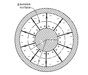
A bare conductor:
Consider a conductor of infinite length, having Q charge per unit length. The electric field will be radially outward or inward depending on the polarity of charge. The field of lines go till infinity where we have assumed potential to be zero.
Applying the Gaussian law:
Plotting the electric field Vs the distance from the center of conductor:
NOTE: The electric field inside the conductor is zero.
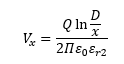
Now, the voltage V and the distance relation:Assuming D as very large distance (infinity)
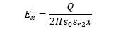
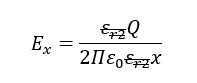
One more parameter is defined, the g, called the voltage gradient, mathematically its value is equal to the electric field and the unit is V per meter. From the expression, its maximum value occurs at the conductor surface always. Let us check what happens when we fill the whole space with a dielectric of constant as εr2, keeping the Q on conductor value same:
NOTE: gmax decreases proportionally.
And the voltage becomes:
Conclusion 1: Keeping the charge and all parameters constant, for increasing value of εr the magnitude of electric field and the voltage developed on conductor decreases. 🙄 WHAT?
An insulated conductor (the case of underground lines):
Now, let us see what happens when we reduce the dielectric material to some finite distance.
a.) Keeping the charge on conductor fixed:
In this case also the electric field will be radially outward or inward depending on the polarity of charge. But the field of lines will not go till infinity, it will terminate at the inner surface of insulator as we have grounded it (assumed potential to be zero). Applying Gauss Law:
Again, plotting electric field (or g) Vs the distance from the center of conductor:
NOTE: Only finite termination of field at +D/2, magnitude remain same as for the infinite dielectric case.
Electric field and gmax remains same in magnitude but lesser than the first case.
Voltage Vs distance:
Here D is finite. Hence, ln(D/d) term will be lesser, so less voltage developed.
Followed from earlier cases, for different insulators (increasing εr), we will see decrease in both electric field and the voltage developed.
Conclusion 2: For same charge on conductor decreasing the depth of insulation will lead to decreased voltage at conductor. 🤷🤐
b.) Now let us keep the voltage fixed:
Effect of varying the material, (increasing εr);
To keep voltage fixed, the charge redistribution on the conductor will take place, charge will increase proportionally as we increase epsilonr2,
Analysing the electric field equation, we can easily see that the magnitude of field will not change,
Conclusion: At constant conductor to earth voltage the electric field (and the gmax) in the dielectric is independent of the material itself.
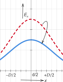
2.Decreasing the insulation depth in this case is extremely important case to consider, keeping in mind the expression of voltage and field:
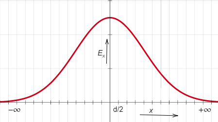
The electric fields:
NOTE: The electric fields will be limited to respective insulation diameter.
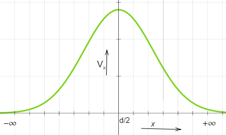
The voltage distribution:
NOTE: Electric field is the gradient of voltage distribution, graph is in agreement of this also.
Conclusion 3: At constant V if we go decreasing the insulation depth than the electric field will go on increasing and eventually will exceed a threshold limit.
HOMEWORK: Calculate for yourself the effect of changing diameter of conductor (d) on parameters.
We will use all these conclusions later directly in designing insulation systems later in the blog.
Two parallel conductors (the case of overhead lines):
Let’s have a revisit to the most general form of an electrical line.
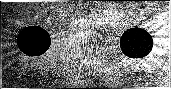
Consider a pair of two infinitesimal small conductors at some potential and carrying some current. If we keep a paper in the plane perpendicular to the plane of conductors and sprinkle some iron fillings, we see a beautiful arrangement of fillings and we know they are along the magnetic lines of the system, as iron always align in the magnetic field.
Now suppose the conductors are only energised not carrying any current and the same experiment is repeated again with mica dust. What would we see?
Begin a dielectric material, the orientation of dust is different and they align along the electric lines of force of the system.
So whenever the power is being transmitted both of the fields are present and this fate of power transmission cannot be achieved if any of them is absent.
Across the whole length of transmission and distribution line, some energy is stored in two forms the electromagnetic and electrostatic field.
The behaviour and dynamics of these two fields can be studied using magnetic circuits and dielectric circuits respectively.
Let us go little off-topic to explore the magnetic circuits and dielectric circuits:
(WARNING: This goes far off-topic you can revisit this section later)
//THIS PARTICULAR SECTION IS UNDER-DEVELOPMENT
ANALOGIES
These two circuits have striking similarities between them.
Magnetic circuit:
The magnetic flux in the set up by the magneto-motive force (mmf) developed by a coil carrying current.
The amount of flux is restricted by the opposing parameter of the circuit called the reluctance which depends on the length, cross-section and magnetic property of the material.
And the reciprocal of the reluctance gives the permeance.
Dielectric circuit:
The dielectric flux is set up by the electromotive force (emf) of the source.
The dielectric reluctance resists the flux, and reciprocal of it represents the capacitance of the dielectric component which is again a function of length, cross-section and the dielectric constant of the material.
MAGNETIC CIRCUIT
DIELECTRIC CIRCUIT
Magnetic flux, 𝜱
Dielectric flux, 𝝋
Magnetic field, B
Electric field density, D
Magnetic field intensity, H
Electric field intensity, E
Magneto-motive force, mmf
Electro-motive force, emf
Reluctance, R
Dielectric reluctance, z
Permeance, P
Capacitance, C
Absolute permeability, 𝝁
Absolute permittivity, 𝛆
Free space permeability,
𝝁o = 4π × 10−7 N⋅A−2
Free space permittivity,
𝛆o = 8.85×10⁻¹² F⋅m−1
Relative permeability, 𝝁r
𝝁r = 𝝁 / 𝝁o
Relative permittivity,
𝛆r = 𝛆 / 𝛆o
MMF= 𝜱R
Emf = 𝝋z
R = l / 𝝁r𝝁oA
z= l / 𝛆r𝛆oA
P = 1 / R
C = 1 / z
Other similarities:
For higher permeability and permittivity of the material the magnetic and dielectric flux is higher respectively for the same mmf and emf.
In the magnetic circuit, the major mmf drop occurs where the permeability is lesser similarly the maximum emf drop occurs in the section where whose dielectric permittivity is lowest.
TWO PARALLEL CONDUCTORS
Even if we don’t understand the field dynamics wholly still, we can at least attempt to apply our previous knowledge of the electric field and voltage distribution for two parallel conductors:
Qualitative description:
Let +Q charge per unit length on surface conductor on right side and -Q charge per unit length on left hand side conductor.
These two will have electric fields which will add to produce the resultant field.
Individual electric field of each conductor
Resultant field in
(-∞, S/2): positive field will be dominant
(@S/2): +ve field and the -ve field will exactly cancel each other at this point
(S/2, ∞): -ve field will be dominant
Rough distribution of field be like:
Votage distribution: Assuming zero potential at S/2 plane. If voltage between +ve wire came out to be V (from reference plane) then the voltage between conductor will be 2V.
Mathematically:
For region, (0, S)
r being very small compared to S, so-
Simplifying E:
Substituting the value of Q:
Potential gradient is maximum at the surface:
NOTE: It is worth remembering IMP formula.
WHAT IS A BREAKDOWN?
The flux density which is dielectric flux per unit area when exceeds a limit the insulation or the dielectric material also starts conducting and electrical energy is wasted, this point is called the breakdown or puncturing of the dielectric or insulation.
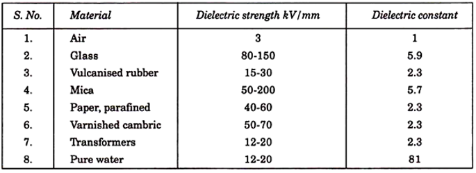
Each material has its own limit of withstanding high-voltage without getting punctured. The strength of insulation is generally expressed in terms of gradient rather than flux density.
Note: There is no relation between the dielectric strength and the dielectric constant of the material.
Here also the dielectric system could be understood by taking the actual mechanical system as an analogy.
Whenever a material is loaded with some force there is deformation, the energy gets stored in material, and these characteristics are represented by the elasticity of the material. Each material has is the ultimate strength after which it breakdown.
Similarly, the potential gradient might be thought of as the force then the flux density as resulting electrical strain, and here permittivity is the electrical elasticity. The energy is stored with increasing force and is given back with decreasing voltage. Rupture occurs when a unit force exceeds the limit.
This concept can be used to easily understand why a highly permeable material when taken in series with a low permittivity material the later one gets ruptured first. As in the mechanical system, the stiffer material (lower elasticity) takes up the major stress and breakdown first.
Breakdown in air i.e. Corona will be explored in detail in next blog.
Sometimes it isn’t enough to just read about it, you have to interact with it! And that’s exactly what you do when you use one of blogs of CEV!!!
You can involve in a technical discussion with our electrical folks:
The second slot of Day 1 of Lumieres’ Professors’ Talk was taken up by Dr. AK Desai, with excerpts from his talk delivered at Ambuja Knowledge Centre City. It was an enthralling and scintillating monologue that had the audience enraptured and asking for more when it ended. Dr. Desai mentioned several enterprises he is on the advisory board of, such as Birla, Tata, etc. He also talked about several projects that he has been associated with including the likes of Surat Airport revamp, the Bullet Train and the Delhi Swami Narayan Temple among several others. The Swami Narayan Temple, designed under the supervision of the late Dr. MD Desai with Dr. AK Desai himself, in particular, is a structural marvel with a geotextile mesh, hand-made and designed to resist an earthquake load of 0.4g and inaugurated by the esteemed Dr. APJ Abdul Kalam.
Delhi Swami Narayan Temple
Ring of Fire
This conversation on earthquake was further extended upon by the mentions of places like the Ring of Fire – a 40,000 km horseshoe shaped area in the basin of the Pacific Ocean where many earthquakes and volcanic eruptions occur- several fracture zones and local earthquake zones like the Kim and Surat Fault line in the Arabian Sea, amongst others. He introduced us to the term PGA which stands for Peak Ground Acceleration and is equal to the largest recorded value of the acceleration at a location, observed on an accelerogram. The massive earthquake that shook Gujarat and most severely Bhuj on 26/1/2001 was caused due to the presence of epicenters around the northern part of the state along the active fault-lines. This, he stressed, wasn’t surprising considering the increment in the number of earthquakes in India with recent studies from 2016 showing that we have an average of 3.5 – 4 earthquakes per day in India, in some capacity. Professor Desai, therefore, also talked about the importance of testing the land before any form of construction. This is because the bearing capacity variations are specific to the site. He also talked about how the tectonic shift in the Indian subcontinent is causing it to move about 50 mm annually to the north-eastern direction, a phenomena directly responsible for giving us the Himalayas due to the Eurasian Plate shift.
Akashi Bridge, Kobe, Japan
Milau Viaduct Paris – Barcelona Bridge
Wadi Abdoun Bridge, Thailand
Russky Bridge, Russia
Rion – Antirion Bridge
Bixby Creek Bridge, California
Dagu Bridge (Sun and Moon Bridge), Tiajin
Cobweb Bridge, Sheffield, England
Sardar Bridge, Bharuch
Mumbai – Worli Sea Link
Confederation Bridge, Canada
Then the conversation drifted to modern engineering marvels. And the first topic to be introduced to the discussion was “Bridges”. He mentioned several types of bridges and their breathtaking examples. The Akashi Bridge in Kobe, Japan, for example, is a Suspension Bridge. Its clearance is about 65.7 m, equivalent to a 20 storeyed building placed below its surface. Dr. Desai mentioned how the initial plan to construct this architectural marvel with a 2000 m central span got foiled when an earthquake reduced it to about 1991 m. The Millau Viaduct Paris-Barcelona bridge, another crowning jewel in the bridge portfolio is a flexible, Cable-Stayed Bridge provided with wind screening and FRP wiring and is the tallest bridge in the world, about 343 m from the ground, which is 19 m taller than the Eiffel Tower. He mentioned several other bridges like the Wadi Abdoun Bridge, a bridge in Thailand which is constructed outside water making it cost-efficient, the Russky Bridge of Russia with its beautiful lighting making it a hot tourist destination spot, the Rion-Antirion cable-stayed bridge in Greece, one of the longest bridges in its category, the Bixby Creek Bridge, a reinforced concrete open-spandrel arch bridge is one of the tallest single-span concrete bridges in the world and is earthquake resistant, owning to its structure, in addition to looking aesthetically beautiful. A cantilever spar cable-stayed bridge is a modern variation of the cable-stayed bridge, some of which have a curved backward pylon back-stayed to concrete counterweights. The famous Sun and Moon Bridge is designed to resist both earthquakes and cyclones. Dr. Desai suggested thinking of shapes that have advanced resistivity to these life-endangering natural phenomenas by thinking outside the box, but staying within the realms of achievable and economically feasible science. The design of the famous Cobweb Bridge, also known as Spider Bridge, located in the city centre of Sheffield, South Yorkshire, England, solves a difficult problem: passing the riverside cycle- and footpath. It counters the issue of traffic constraints often noticed on bridges. Professor Desai then came back home to the famous and beautiful Sardar Bridge in Bharuch, which is shaped like multiple tuning forks supporting the cables running through and its design is Extradosed Cable Stayed Bridge wherein the height of the pylon is smaller than in the case of regular Cable Stayed Bridge. He also talked about how modern day engineering has adopted the various available designs to create a hybrid, which offers more stability and can help construct large span bridges. The combination of Cable Stayed Bridge and Suspension Bridge is one such example. These days India has also adopted the famous Precast Segmental Construction technique in which bridges are constructed at manufacturing sites and then brought along to the place over the river and hung on launching girders and slid across to create the whole bridge step by step and with minimal effort. The famous Mumbai-Worli Sea Link is one such example. Canada solves its bridge construction woes caused due to expansion of ice using modern engineering methods, too. Since, major loading through ice gives tremendous pressure to bridges, there, they have adopted the Cantilever construction in bridges such as the Confederation Bridge.
Fieranilano, Milan, Italy
Scientific advancement has made it possible for us to create deployable structures that can change shape so as to significantly change its size such as in the cases of umbrellas, some tensegrity structures, bistable structures, some Origami shapes and scissor-like structures. Dr. Desai recommends reading books and referring to the works of Dr. Devdas Menon, Professor of Structural Engineering at IIT Madras who has several patents to his credit, some even in the field of Biomedical Engineering. Post that Professsor Desai talked about other engineering marvels such as the Fieramilano which is the largest civil engineering project built in Europe in recent years with a gross floor area of 530,000 square meters, a land area of 2,000,000 square meters, and a 5-kilometer perimeter. It is a trade fair and exhibition organizer headquartered in Milan, Italy. It is the most important trade fair organizer in Italy and one of the largest in the world. The World Trade Center, another engineering innovation had an innovative “tube” design, with a perimeter support structure joined to a central core structure with horizontal floor trusses, a construction methodology hitherto unknown. The Petronas Tower in Malaysia used bridges and dampers to create their architectural beauty. It has a bridge connecting the two towers on the 41st and 42nd floor making it the world’s tallest 2 story skybridge, providing structural support to the towers and also acting as a potential escape route in case of an emergency from one tower to other. Back home, in Mumbai, the Lodha group has constructed the famous World One Tower which, upon completion is expected to be the world’s 2nd highest residential skyscraper in the world after 432 Park Avenue in New York.
Petronas Tower, Malaysia
World One Tower, Mumbai
Park Avenue, New York
Dr. Desai stated that the most important thing to be considered while constructing anything is safety and to that end dampers must be used to provide structural integrity. Additionally, the material used is also extremely important. For example, using Stainless Steel over Carbon Steel has several advantages. It doesn’t stain, corrode or rust as normal carbon steel. Close home, polypropylene construction fibre has been used for construction of the road in front of the SVNIT campus instead of steel, to delay and control the tensile cracking of the composite material. In Japan, fibre is used to reduce deadload and transportation cost, in addition to providing strength. This was also put to test by Professor Desai and the team that tested fibre enforced roads in Kargil, realizing that it doesn’t crack as readily and is, therefore, durable and more reliable for the harsh climate of Kargil. This innovation is not just limited to creating more efficient and reliable techniques. They also help enhance the safety of places prone to dangerous phenomena such as the mountains with recurring cases of landslide and boulder tumbles, endangering the lives of people and disrupting the roads built along these mountains. So, in places like Saputara, they have built rock fall protection fences. In high altitude places where snow causes accidents, they have created snow fences that could stop the snow from sliding from the mountains onto the roads, thus, making preventing them from getting slippery. The India-Pakistan border is being fitted with Gabions to prevent salt from Pakistan to wash up to Gujarat and Rajasthan during heavy rainfalls that deposit as white salt. These days the R&D teams across the globe are also working at creating solution to our environmental woes by looking for substitute technology and materials that reduce pollution and harmful emissions. Cement manufacturing is one such area where CO2 and CO emissions increase, therefore, alternative materials and substances are being developed to offer a greener alternative. Additionally, plastic waste disposed off in green ways can be utilized for various purposes with the right kind of economically viable method.
Team CEV has conducted a three-day event where top professors of SVNIT shared their excellent research work with enthusiastic students. Professors have given some time from their precious and hectic time schedule for our event. The main purpose of the event is to give students an insight into various fields of research and help them find their field of interest to work on and also to give knowledge of different professors that can’t be shared in the classroom due to academic schedules.
The event has been inaugurated by Dr.Jignesh N. Sarvaiya, Associate Professor – Electronics departments, who also gave the first talk of the event. The topic of the talk was “Image Processing”. Dr Sarvaiya gave some excellent insight into the whole back story of an Image. And also explained how are images captured and what exactly are pixels. Some insights into the algebra involved behind the processing of an image.
The next talk was given by Dr A. K. Desai, Professor – Applied Mechanics Department. His topic was “Recent Advances in Structural and Geotechnical Technologies”. Dr. Desai showed us the importance of structural engineering in solving the many present problems of traffic in more economic and less inconvenience to the public. Also, the talk covered the contribution of structural engineering in the recent development of buildings, bridges and flyovers and many more.
The final talk of the 1st day was given by Dr Shriniwas Arkatkar, Associate Professor – Civil Engineering Department. The topic of the talk was “A look at transport of the future in developing countries”. The talk basically covered the present transport problems and some possible solutions to these problems in the future. Dr. Arkatkar stressed much on interdisciplinary projects in developing more standard solutions and he strongly believes that these problems can not be solved by any single engineering department.
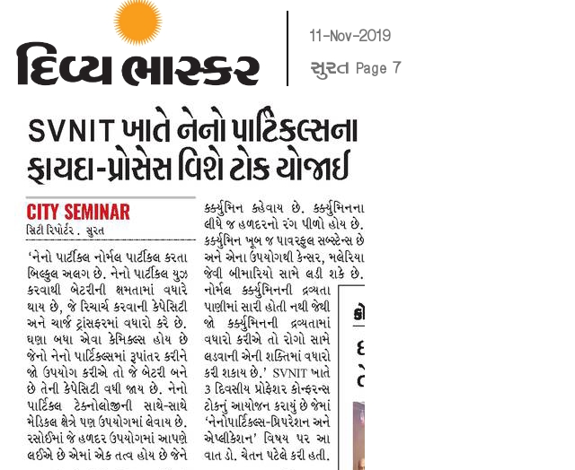
The kick start to the 2nd day of Lumieres- Wisdom Week was given by Dr. Chetan Patel, Associate Professor- Chemical Engineering Department. The topic of the talk was “Nanoparticles”. Dr Patel explained the methods of preparation of nanoparticles and also challenges faced in the same. The importance of nanoparticles and how materials behave in the size of nanoparticles varies from its normal known particles and also how the nanoparticles are contributing in different fields of development are discussed.
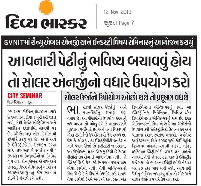
The next talk was given by Dr P.V. Bhale, Assistant Professor – Mechanical Engineering department. The topic of the talk was ”Renewable Energies and Industries”. In the recent times of very high rate of depletion of fossil fuels, a high number of researches are being carried out to develop an alternative fuel, most probably from renewable sources with the intention to don’t harm the environment. Dr Bhale explained different potentials of available renewable sources and challenges faced to make it a primary source of energy and economically easy to produce energy from such fuels.
The final talk of the 2nd day was given by Dr Vipul Kheraj, Associate Professor – Applied Physics Department. The topic of the talk is” Light – A Fascinating Probe to the Universe”. Dr Vipul has explained what and how fascinating things can be proved by using light, like short bending of space time graph due to massive celestial bodies. The concept behind G.P.S. The LIGOs which were built to determine the passage of Gravitational waves, LIGO is basically a massive interferometer built in 4km X 4km radius.
The last day of the LUMIERES- Wisdom Week was started by Dr. Jayesh Dhodiya, Associate Professor – Applied Mathematics and Humanities Department.The topic of the talk was “Application of Mathematical Modelling in Engineering Problems “. Dr Dhodiya has excellently explained how to see an engineering problem and how to approach the solution of the problem. The talk gave an idea of the importance of Mathematical Modelling to solve any real-life problems, without which it will be more difficult to find out the best possible solution to the problem.
The last talk of the LUMIERES – Wisdom Week was given by Dr A.K. Panchal, Professor- Electrical Engineering Department. The topic of the talk was “Solar Cells and Renewable Energy”. Dr Panchal provided all the statistics regarding usage of fuels and need of renewable energy to come into picture predominantly. Also he explained why it is still difficult to bring renewable energy in large scale, economic factors and efficiency factors and many other factors which play a dominant role in these pictures. The talk also gave an idea about the making of solar cells, materials needed, factors to be considered and many more.
With this series of talks, LUMIERES – Wisdom Week 1.0 has been concluded. Team CEV is pretty much sure that everyone got so much to learn from the professors and also got to know the professors.
Firmest edition of LUMIERES – WISDOM WEEK has attracted a lot of attention and news.
Reading Time: 6minutesIn the very first Wisdom Week – LUMIÈRES conducted by CEV, Dr. Jignesh N Sarvaiya of Electronics Engineering Department gave the students some really interesting insights into Digital Image processing. Here is a brief summary of the topics covered by him.
What is a digital image?
A digital image is a representation of a two-dimensional image as a finite set of digital values, called picture elements or pixels. Pixel values typically represent gray levels, colours , heights, opacities etc. Digitization implies that a digital image is an approximation of a real scene. Common image formats include black and white images, grayscale images and RGB images.
What is Digital Image Processing (DIP)?
Digital Image Processing means processing digital image by means of a digital computer. It uses computer algorithms, in order to get enhanced image to extract some useful information.
The continuum from image processing to computer vision can be broken up into low-, mid- and high-level processes which are explained below.
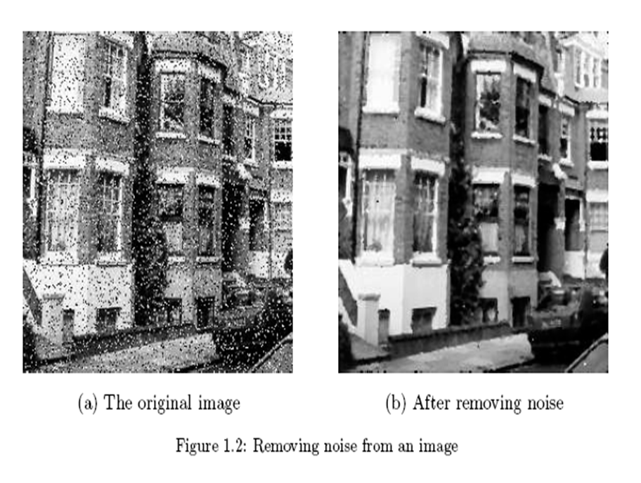
Low Level Process: where the input as well as the output is an image. Examples include noise removal and image sharpening.
Mid Level Process: where the input is an image and output is attribute. Examples include object recognition and segmentation.
High Level Process: where the input is attribute and output is understanding. Examples include scene understanding and autonomous navigation.
Representing Digital Images
An image may be defined as a two-dimensional f(x,y), where x and y are spatial coordinates and the amplitude of f at any pair of coordinates (x,y) is called the intensity of the image at that point.
A digital image can be represented as a M x N numerical array. The discrete intensity interval is [0, L-1] where L=2k
The number of bits (b) required to store M × N digitized image is given by b = M × N × k.
Why do we need DIP?
Image processing is a subclass of signal processing concerned specifically with pictures which improves image quality for human perception and/or computer interpretation.
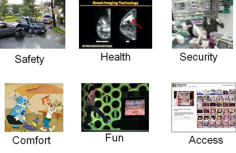
It is motivated by major applications such as improvement of pictorial information for human perception, image processing for autonomous machine applications, efficient storage and transmission.
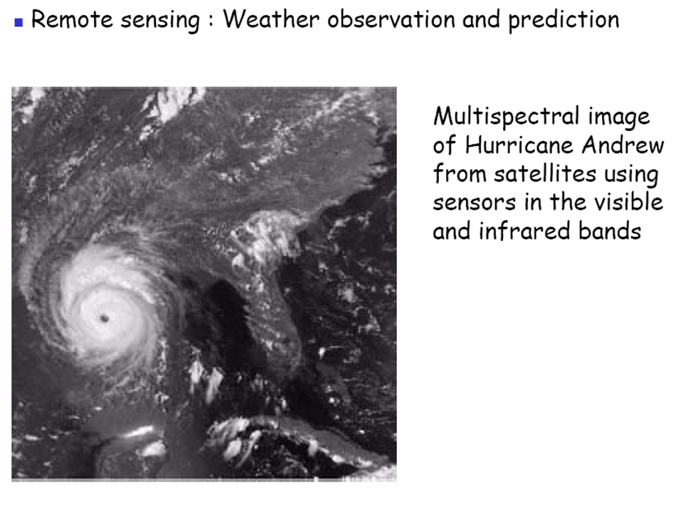
DIP employs methods capable of enhancing information for human interpretation and analysis by noise filtering, content enhancement, contrast enhancement, deblurring, remote sensing etc.
Fields Using DIP
Radiation from the electromagnetic spectrum
Acoustic
Ultrasonic
Electronic in the form of electron beams used in electron microscopy
Computer synthetic images used for modelling and visualisation
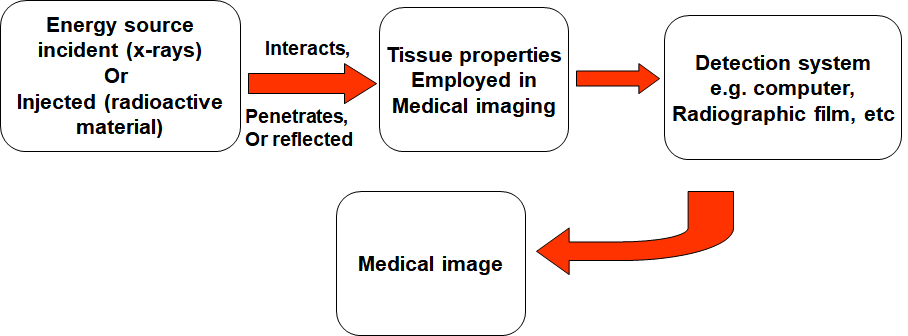
DIP in Medicine
Medical imaging is the technique and process of creating visual representations of the interior of a body for clinical analysis and medical intervention, as well as visual representation of the function of some organs or tissues.
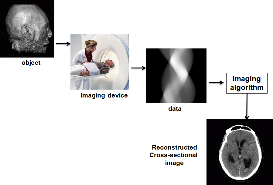
For example, we can take the MRI scan of canine heart and find boundaries between different types of tissues. We can use images with gray levels which represent tissue density and use a suitable filter to highlight the edges.
OVERALL CONCEPT
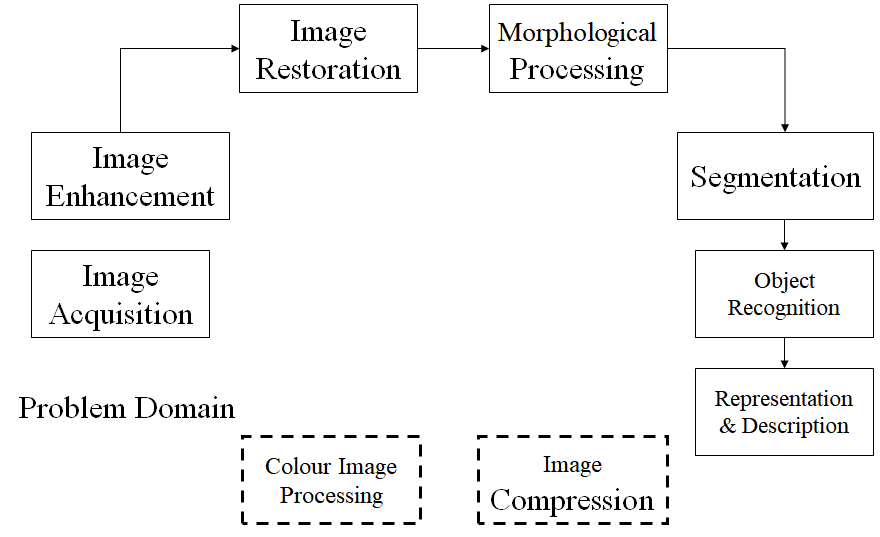
Key Stages in DIP
Let us understand these stages one by one.
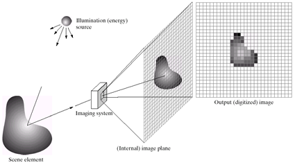
Image Acquisition: An image is captured by a sensor such as a monochrome or camera and digitized. If the output of the sensor is not in digital form, it is digitized with an analog to digital convertor. A camera contains two parts: a lens which collects appropriate radiation and forms a real image of the object and a semiconductor diode which converts the irradiance of an image into an electrical signal.A frame grabber requires circuits to digitize electrical signals from imaging sensor to a computer’s memory.
Image Enhancement: It is used to bring out obscured details or highlight the features of interest of an image. It is commonly used to improve quality and remove noise from images.
Image Restoration: It is the operation of taking a corrupt/noisy image and estimating the clean, original image. Corruption may come in many forms such as motion blur, noise and camera mis-focus.
Morphological Processing: Morphological operations apply a structuring element to an input image, creating an output image of the same size. The value of each pixel in the output image is based on a comparison of the corresponding pixel in the input image with its neighbors.
Segmentation: It is the process of partitioning a digital image into multiple segments to simplify and change the representation of an image into something that is more meaningful and easier to analyze.
Object Recognition: Object recognition is a technique for identifying objects in digital images. It is the key output of deep learning and machine learning algorithms.
Description and Representation: After an image is segmented into regions; the resulting aggregate of segmented pixels is represented & described for further computer processing. Representing region involves two choices: in terms of its external characteristics (boundary) in terms of its internal characteristics (pixels comprising the region).
Image Compression: It is applied to digital images to reduce their cost for storage or transmission.
Colour Image Processing: A digital color image is a digital image that includes color information for each pixel. The characteristics of color image are distinguished by its brightness and saturation.
Knowledge Base: Knowledge about a problem domain is coded into an image processing system in the form of a knowledge database.
Types of Digital Images
Intensity image or monochrome image: Each pixel corresponds to light intensity normally represented in gray scale.
Color image or RGB image: Each pixel contains a vector representing red, green and blue components.
Binary image or black and white image: Each pixel contains one bit, 1 represents white and 0 represents black.
Index image: Each pixel contains index number pointing to a color in a color table.
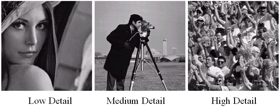
Image Resolution
Resolution refers to the number of pixels in an image. The amount of resolution required depends on the amount of details we are interested in. We will now take a look at Image and Intensity Resolution of a digital image. Spatial resolution: It is a measure of the smallest discernible detail in an image. Vision specialists state it with dots (pixels) per unit distance, graphic designers state it with dots per inch (dpi). Intensity Level Resolution: It refers to the number of intensity levels used to represent the image. The more intensity levels used, the finer the level of detail discernable in an image. Intensity level resolution is usually given in terms of the number of bits used to store each intensity level.
Computer Vision: Some Applications
Optical character recognition (OCR)
Face Detection
Smile Detection
Vision based biometrics
Login without password using fingerprint scanners and face recognition systems
Object recognition in mobiles
Sports
Smart Cars
Panoramic Mosaics
Vision in space
Hope you got some insights into digital image processing and computer vision. Thanks for reading !
Why Management is an IMPORTANT study for Engineering Students?
“successful engineering projects rely more on non-technical skills than technical skills.”
It’s not like that technical skills aren’t important, because the car we drive will not be able to run without technical skills of an engineer and it will not be safe to drive until a skilled Automobile engineer works on it.
Any skilled engineer working on any particular project will not be successful unless there is an equally skilful project manager involved in it. Doesn’t feel right? Project Management Institute’s (PMI) 2016 report The High Cost of Low Performance: How will you improve business results? Showed that $122 million was wasted for every $1 billion invested due to poor project performance. So gaining some management skills to an engineer is very helpful.
What is Organisational behaviour?
Organisational behaviour (OB) is an important topic in the studies of management. OB is a study & application of knowledge about human behaviour as individuals and in groups- in the organization- strives to identify ways in which people can act more effectively. OB is the field of study which investigates the behaviour of the individual group and organizational structure. Why do we need to learn OB?
Knowledge is replacing infrastructure.
In past years companies are interested in developing the infrastructure but later they realise that knowledge is more important than infrastructure.
Self-Leadership is succeeding command control management.
Self-motivated man does not want leader-ship so it reduces the cost of supervisors.
Companies are looking for employees with emotional intelligence, not just technical smartness.
Companies are not hiring employees with high IQ but also for their high Emotional Intelligence EQ, because a person with high EQ can handle the workload and give his best performance in a critical situation.
Globalisation has become the mantra of corporate survival.
Before the globalisation, the companies were only selling their products to their local areas but after globalisation that companies selling their products to different countries which requires the understanding of global policies.
Organisational behaviour includes topics like psychology, sociology, political science etc. Psychology includes the study motivation, humanities, emotions of an employee. Sociology is the study of one kind of working environment. Political Science helps to understand the different government policies, which can be helpful for business.
Reading Time: 11minutesGENERAL WORKING PRINCIPLE OF A WASHING MACHINE:
We put our clothes in, pour some water, then some detergents. The wash cycle begins, the mixture is strongly agitated, the dirt gets dissolved by detergent action, then we drain the dirty water. Again fresh water is poured, agitation begins, hence the clothes gets clearer after repeating a few cycles.
Afterwards, the clothes are transferred to the spin section, the unidirectional fast spinning motor rotates to squeeze water out of clothes. Hence clothes become drier and finally, we use natural or forced evaporation to get clean, dry and fragrant clothes.
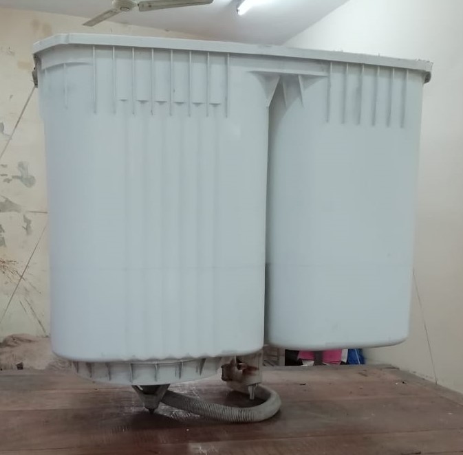
Welcome, this is a tear-down of a semi-automatic washing machine. The company is Electrolux, 8 Kg, and top- load type.
SEMI-AUTOMATIC MACHINES:
Working:
Semi-automatic involves the involvement of the user itself to manually operate various procedures of the process.
Water and detergent are poured by the user itself
Timer and no of repetitions for the wash cycle is set again by the user
The user himself has to transfer the clothes from the wash section to the spin section
Going through this general principle we have got two major circuitry for our machine:
Electrical circuitry to generate the mechanical force of rotation and plumbing circuitry to regulate the flow of water.To have a controlled motor operation we require the following components:
Electrical circuits:
Timers
Wash Motor
Spin Motor
To get efficient cleansing action we require following elements for Plumbing circuit
Basic frame
Spin gasket
Agitator or Impeller
Filter
PLUMBING CIRCUIT
The basic frame:
The wash and spin cabin
This frame provides two separate cabins for wash and spin section. The inner side of the wash section have smooth projections for rubbing of clothes and spin cabin is simply there to collect the water ejecting from the spin-gasket.
2. Spin Gasket:
The spin cabin is utilised for drying clothes to some extent after washing and rinsing.
The spin motor of higher RPM rotates the laundry in the spin gasket. The large centripetal forces push the water through the small holes on the dyer gasket. The water gets collected on the outer spin cabin and is drained out.
3. AGITATOR Vs IMPELLER:
One would find agitator and impeller arrangement in the top-load machine only. They work almost in a similar way but impact the fabric in different ways.
The agitator is a screwed, finned vertical shaft driven by the wash motor to rotate back and forth. Clothes rub against the agitator and get cleaned.
The impeller is a low profile cone or disc and driven by the wash motor to rub the clothes among each other and produce the cleansing action. The holes on the disc drain the water after the wash or rinse cycle is over.
Impeller
4. Filter:
ELECTRICAL CIRCUIT
Technically various motor technologies are used in these devices like DC series, and highly efficient BLDC, but in today’s time the most commonly used motor is still single-phase induction m/c, yes the same machine that runs the fans, water coolers, exhaust, small water pumps, etc.
For washing machine purposes we need to have various controlled characteristics:
The motor must be producing high starting torque,
it must reverse the direction of rotation after a fixed time period and,
and must be efficient.
Out of all these points, fundamentally direction reversal is most important, as the clothes or water will be spilt out and very poor cleansing action will be obtained if the motor is operated in one direction. To understand how direction is reversed it is important to understand the principle of a single-phase motor.
This fan, for example, is a single-phase motor, and if we connect this motor in any way to the plug the rotation is always in one direction.
These motors have a very simple structure and low maintenance. But has poor efficiency, around 50-60 %. They will slowly become obsolete in the coming 5-10 years.
TIMER:
For direction reversal as well as keeping the time, TIMER has a job to do. A normal semi-automatic WM uses a mechanical timer device to control the motor operation.
So let’s understand the timer first.
A timer as shown consist of four-terminal:
Black: is the mains wire
Brown: is the buzzer wire
Yellow and red are two output wires each becomes the live terminal for half clock cycle with little delay in between.
So here is a demonstration circuit for the timer driving two bulbs alternatively.
DIRECTION REVERSAL:
Let us now use the timer to reverse the motion of our washing machine motor represented by this simple single-phase table fan same machine with lower power rating.
Idea:The direction of rotation of the motor can be reversed if the current in the two windings (main and auxiliary) are made to lag and lead each other in a cyclic way. This can be done if we connect the capacitor in series with the main winding and in the next cycle connect the capacitor with the auxiliary winding. This can be simply done if just exchange the live connection to the capacitor across the capacitor terminals. We also know the timer exchanges the live wire between its two terminals in a periodic way.
Using the capacitor in winding 1, suppose motion to be clockwise:
2. Using the capacitor in the winding 2, the direction of rotation of the magnetic field is reversed:
3. Now just simply superimpose both of them by using the wash timer:
4. Finally, we obtain an electrical circuit for direction reversal:
And here is the actual demonstration model used in the tear-down event:
TOP LOAD AND FRONT LOAD:
A top-load machine like this one, the clothes and water are fed into a fixed vertically mounted wash cabin with agitator or impeller at the centre which is driven by a single-phase induction motor.
In case of a front-loaded machine, the clothes are fed into a horizontally mounted drum. In this case, the whole water-tight drum rotates back and forth, and the plastic paddles mounted on the drum slosh the clothes. Mostly the semi-automatic washing machines are top-load. And we have two options for the fully-automatic machine, they are available in both top and front load.
Which is better in case of a fully-automatic washing machine?
TOP-LOAD
FRONT-LOAD
Cheaper
More clothes can be washed in one wash cycle as a drum can be filled to the top.
Ergonomic
Less water consumption
Less energy
Central agitator turns the clothes roughly
Gentle gravity aided wash
Clothes can be put inside in between the wash cycle
Rugged construction
Less noisy
More features
FULLY-AUTOMATIC:
Here come the wonders of 21st century the ELECTRONICS. In general, any electrical systems when accompanied (or controlled) by electronics we get a real high efficient, flexible, magical and great user- friendly products. Fully Automatic gives you the elite experience of washing your clothes at a very low cost in terms of water, energy and effort used, and give ultra-clean fabrics. The whole machine operates by just selecting a few options and you finish washing clothes even without getting your hands wet.
The striking difference between the semi and fully automatic machines is the ability of a fully automatic machine to operate completely on its own once you have selected the fabric type. The embedded micro-controller operates various components in a controlled and synchronous way according to the already saved programs in its memory.
Look at the dashboard of a typical fully automatic washing machine (IFB, 7.5 Kg ):
You have a total of 10 different types of programs available and also you have the flexibility to set your own programs. The machine automatically set the wash, rinse and spin cycle (which includes the time and RPM), the amount of water and detergent, temperature of the water and even gives an option of delay time.
A TRAIL RUN:
Suppose you selected smart sense and pressed the start button then following is the routine the machine is subjected to go:
To determine the time and RPM it necessary to know the amount of fabric in the machines, so the sensors first sense the weight and then accordingly set the timers.
Then the micro-controller turns on the heating element and valve for inlet water and pours the detergent as required.
The wash cycle begins, the flappers continuously rub the fabrics to remove stains and dust.
Dirty water drains out.
Rinse cycle begins and is repeated several times based on load.
Then the tub is rotated at exceedingly high speed to force the water out through the holes on the inner drum.
The machines give a buzzer sound indicating the wash is over.
The circuit design of fully automatic machines is beyond the scope of this discussion and for the writer also to understand and comprehend.
THE GREAT INDIAN MARKET:
Our country has shown a pretty healthy economic growth in the past 10-15 years.
We were fifth-largest economy and also the fastest growing economy in 2018 (however current slowdown has dragged us down to 7th position in both categories),
By this time the consumer durable has built a massive market of around 31.48 billion US dollar in 2017.
We are the world’s second-largest smartphone market.
We are the world’s third-largest television market.
Now, all the range of electrical and electronics products that you see in a typical household are broadly classified into two categories:
WHITE GOODS: in other words Consumer appliances -These goods category include heavy-duty major equipment, for example, refrigerator, washing machine, induction cookers, microwave ovens, electric fans, etc.
BROWN GOODS: Consumer electronics– Relatively small electronics goods like smartphones, TV, radio, digital camera, audio systems, etc.
Goods product like TV and refrigerator has reached inflexion point (saturation) with 75% and 30% Indian homes owning them, while products like AC and washing machine still hangs at relatively lower penetration of around 4% and 11% respectively. Whereas countries like China have AC and washing machine penetration up to 60% and 40%, clearly India still has a huge untapped potential for these goods.
The year 2018 saw a sale of 6.5 M units of Washing machine in India. So to analyse the Indian market for WM let us look at a few parameters: demand drivers, major manufacturers, technology type and new developments:
Demand drivers
Urban India:
Urban India shares the major demand for consumer durable market.
Particularly washing machine user most lives in few concentrated regions, 1/3rd of the user lives in just six major cities.
Reason for such demand patterns is due to the high living standards and also the increasing disposable income of middle and upper-class society of first and second-tier cities. Reduced cost and elite technology has led for reduced replacement time also.
Rural India:
Rural India does not show such great numbers but surely with increasing modernisation the consumer durable have now begun to be accepted as a necessity rather than a luxury. Here following opportunities are there:
Electrification:Govt initiative to strengthen the rural electric system would surely play a detrimental role in future.
Changing lifestyle:Rural India has also witnessed the pattern of changing lifestyles. There has been a significant increase in nuclear families, increase in awareness, and easier access to services, all of these makes a perfect cocktail for a consumer durable to gain some weight.
Working women:Women in rural India have also begun stepping out which will generate the immediate need for laundry systems.
Growing disposable income: The current slowdown has hit rural India the hardest- rural wage has stagnated for a while, FMCG have performed very poorly and overall demand has shown a negative slope, but still hopes of recovery from this disaster is there which will ultimately bring Indian economy back on track with more thrust.
Major manufacturers:
Multinational: The foreign players like South Korean LG and Samsung, Swedish Electrolux, Chinese Heir, Japanese Hitachi and Panasonic and American Whirlpool have already littered the India urban market with their cutting-edge, advanced smart-technology laundry system, which is more phantasmic in urban Indians.
Indian players: They are equally capable of producing advanced washing machine but they all lag at brand popularity. The giants like Videocon and IFB have also shifted their focus on the rural market.
Technology type:
Fully automatic: At a minimal increase in cost compared to semi-auto counterpart the fully automatic washing machine comes with far better improved and elegant user service. Thus fully-auto machines sales contribute significantly to the overall sale of washing machines.
Semi-automatic: Having the advantage of low cost and simplicity they find their place in the rural region where current demands are not explosive like in urban regions.
New developments and updates:
In October 2017 Flipkart launches its consumer appliances label called MARQ for selling products like ACs, WMs, etc.
2. Godrej set a 400 crore expansion plan in 2018 for washing machine industry, increased production capacity from 4 lakh units to six lakh in Mohali manufacturing unit.
NEW FEATURES:
Here comes the most interesting portion of the blog. In this globalised world, companies face great competition to win the consumer’s heart. And this is the engine fuel of modern innovation – to always keep one’s product a step ahead of others. Fortunately we the consumers get to see a modern marvel in this process. These days (2019) the fully automatic machines have become quite smart along with their conventional benefits of increasing the water economy, energy efficiency, child lock mechanism and user-friendly services, they now provide exciting features though at the cost of a significant amount of money.
To name a few:
LG Twin-wash introduced in 2015 have both front load and top load for washing two different types of fabric at the same time. (60,0000 INR)
Samsung Addwash can add fabric during wash cycles and gives the WiFi connectivity with your smartphone to operate your machine remotely and get the status. (46,000 INR)
LG Signature provides features of extremely low noise and vibration, auto detergent dosing system and screen touch control panels.
Finally, Panasonic sustainable maintainer which washes, drying and folding the clothes, however, the product was kept in a trade show at Berlin and is still to hit the market.
You can also explore some of the newest washing machines entering the market using the link below: